Convenient-to-use power cable corrector

A power cable and corrector technology, applied in the field of cable correction equipment, can solve problems such as repeated disassembly and assembly, and achieve the effects of improving the scope of application, reducing friction, and simple structural design

Active Publication Date: 2021-02-09
DEZHOU LINGCHENG POWER SUPPLY CO OF STATE GRID SHANDONG ELECTRIC POWER CO
View PDF15 Cites 0 Cited by
  • Summary
  • Abstract
  • Description
  • Claims
  • Application Information

AI Technical Summary

Problems solved by technology

[0004] The invention provides an easy-to-use power cable calibrator, which is used to solve the problem of repeated disassembly and assembly in the calibrating process, and achieves the beneficial effect of continuous calibrating without disassembly

Method used


Image

  • Convenient-to-use power cable corrector
  • Convenient-to-use power cable corrector
  • Convenient-to-use power cable corrector

Examples


Embodiment 1

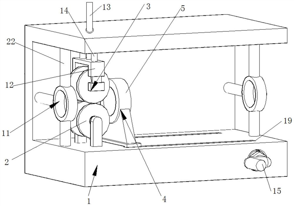
[0033] An easy-to-use power cable straightener such as figure 1 As shown, it includes a base 1 with a C-shaped cross section, a fixing mechanism, a flattening mechanism and a moving structure. The flattening mechanism includes a lower pulley 2 and an upper pulley 3. One side of the base 1 is provided with a lower pulley 2, and the other Side is provided with the upper pulley 3 of adjustable position, and upper pulley 3 is corresponding with lower pulley 2 positions.

[0034] Such as figure 1 and Figure 5 As shown, one side of the upper pulley 3 is provided with a connecting frame 12, and the connecting frame 12 is provided with an adjusting rod 13 threadedly connected with the base 1; Turn the adjustment rod 13 to change the height of the connecting frame 12, and then change the distance between the upper pulley 3 and the lower pulley 4, so that it is suitable for cables of different specifications; and the adjustment rod 13 is screwed to the base 1, and is in a locked stat...

Embodiment 2

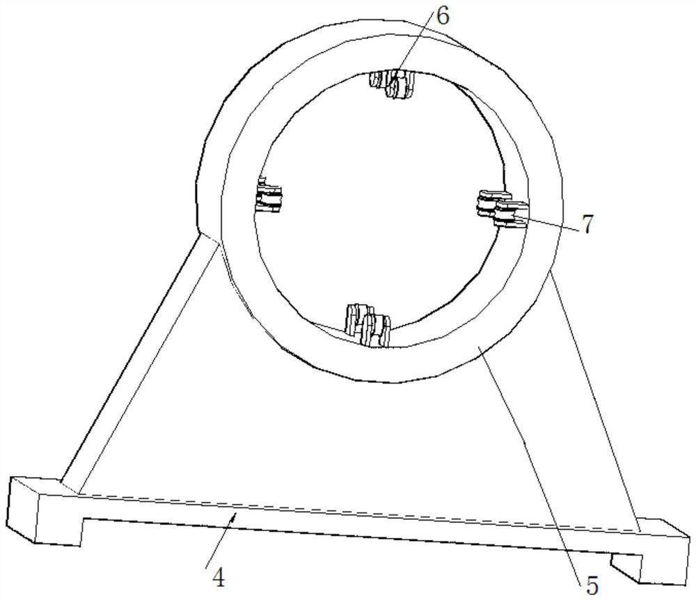
[0044] On the basis of Example 1, such as Figure 7 As shown, the moving structure further includes a telescopic rod 20 and a connecting block 21 , the telescopic rod 20 is provided on the lower side of the sliding seat 4 , and the other side of the telescopic rod 20 is movably connected to the connecting block 21 located on the side of the conveyor belt 18 . The connecting block 21 is always connected with the telescopic rod 20 when the conveyor belt 18 moves, and the user can turn the handle in one direction to realize the reciprocating movement of the slide seat 4, so as to move the cable from the flattening mechanism to the other side, which is convenient to use.

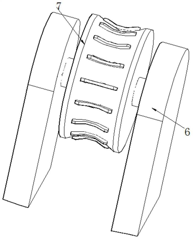
[0045] There are two sets of pawls 10 on the runner 7 , one set of pawls 10 is located in the wheel groove 8 , and the other set of pawls 10 is located between the outer side of the wheel groove 8 and the friction wheel 7 . One set of pawls cooperates with the wheel groove 8 to form a ratchet pawl structure, so ...


PUM


Abstract

The invention provides a convenient-to-use power cable corrector which comprises a base, a fixing mechanism, a flattening mechanism and a moving structure, wherein the section of the base is C-shaped;the flattening mechanism comprises a lower pulley and an upper pulley; the lower pulley is arranged on one side of the base; the position-adjustable upper pulley is arranged on the other side of thebase; the position of the upper pulley corresponds to that of the lower pulley; the fixing mechanism comprises a sliding seat, a fixing ring, fixing plates, friction wheels, wheel grooves, rotating wheels and pawls; the sliding seat which is in sliding fit with the base is arranged on the base; the fixing ring is arranged on the sliding seat; the friction wheels which are in contact with a cable are mounted on the inner side of the fixing ring through the fixing plates; the wheel grooves are formed in the fixing plates; the rotating wheels which are coaxial with the friction wheels are mountedin the wheel grooves; the pawls are movably mounted on the rotating wheels through a torsional spring; the moving mechanism used for moving the sliding seat in a reciprocating manner is arranged on the base; and guide rings are arranged on two sides of the base.

Description

technical field [0001] The invention belongs to the technical field of cable correction equipment, in particular to a convenient power cable correction device. Background technique [0002] A cable is an electrical energy or signal transmission device, usually composed of several or several groups of wires. Because the cables are usually very long, they usually need to be curled up for transportation during transportation, which will cause the cables to bend, and the cables usually need to be kept straight when they are used. At this time, the cables need to be corrected for use. , curved cables usually cannot be used directly. [0003] In general cable calibration equipment, after a section of cable is calibrated, the cable needs to be disassembled from the fixing device, and then the new end should be re-fixed on the equipment. time, the efficiency is very low. Contents of the invention [0004] The invention provides an easy-to-use power cable calibrator, which is us...

Claims


Application Information

Patent Timeline
Patent Type & Authority Applications(China)
IPC IPC(8): B21F1/02B21F23/00
CPCB21F1/02B21F23/00Y02W30/82
Inventor 汪洋许春辉冯永彬杨海荣臧树宝赵紫铭王朝香闫辉宫勇飞瑾晓杰
Owner DEZHOU LINGCHENG POWER SUPPLY CO OF STATE GRID SHANDONG ELECTRIC POWER CO
Why Eureka
Try Eureka