Device capable of performing pressure welding on copper bar for new energy automobile

A technology for new energy vehicles and copper bars, applied in welding equipment, non-electric welding equipment, metal processing equipment, etc., can solve the problems of inaccurate welding parts, low degree of automation, and high labor intensity of workers, so as to prevent loosening and automation High, accurate welding position effect

Inactive Publication Date: 2021-02-09
WUHU HENGKUN AUTO PARTS
View PDF7 Cites 4 Cited by
  • Summary
  • Abstract
  • Description
  • Claims
  • Application Information

AI Technical Summary

Problems solved by technology

[0002] Both ends of the soft connection copper bars need general pressure welding to make the connection between the copper bars stable, to prevent the copper bars from falling off and scattered in the subsequent processing process, and even cause accidents during use; the existing soft connection copper bars are pressure welded It mainly relies on manual hand-held copper bars for welding, which has a low degree of automation and high labor intensity for workers. At the same time, there are inaccurate welding positions, which leads to inaccurate welding ranges and seriously affects the yield rate of copper bars; traditional pressure welding equipment is not equipped with protective devices. It is very easy to be injured after misuse, so a device capable of pressure-welding copper bars for new energy vehicles is designed to solve the above problems

Method used


Image

  • Device capable of performing pressure welding on copper bar for new energy automobile
  • Device capable of performing pressure welding on copper bar for new energy automobile
  • Device capable of performing pressure welding on copper bar for new energy automobile

Examples


Embodiment Construction

[0019] In order to enable those skilled in the art to better understand the technical solutions of the present invention, the present invention will be described more clearly and completely below in conjunction with the accompanying drawings in the embodiments. Of course, the described embodiments are only a part of the present invention. Not all, based on this embodiment, other embodiments obtained by those skilled in the art without creative efforts are all within the protection scope of the present invention.

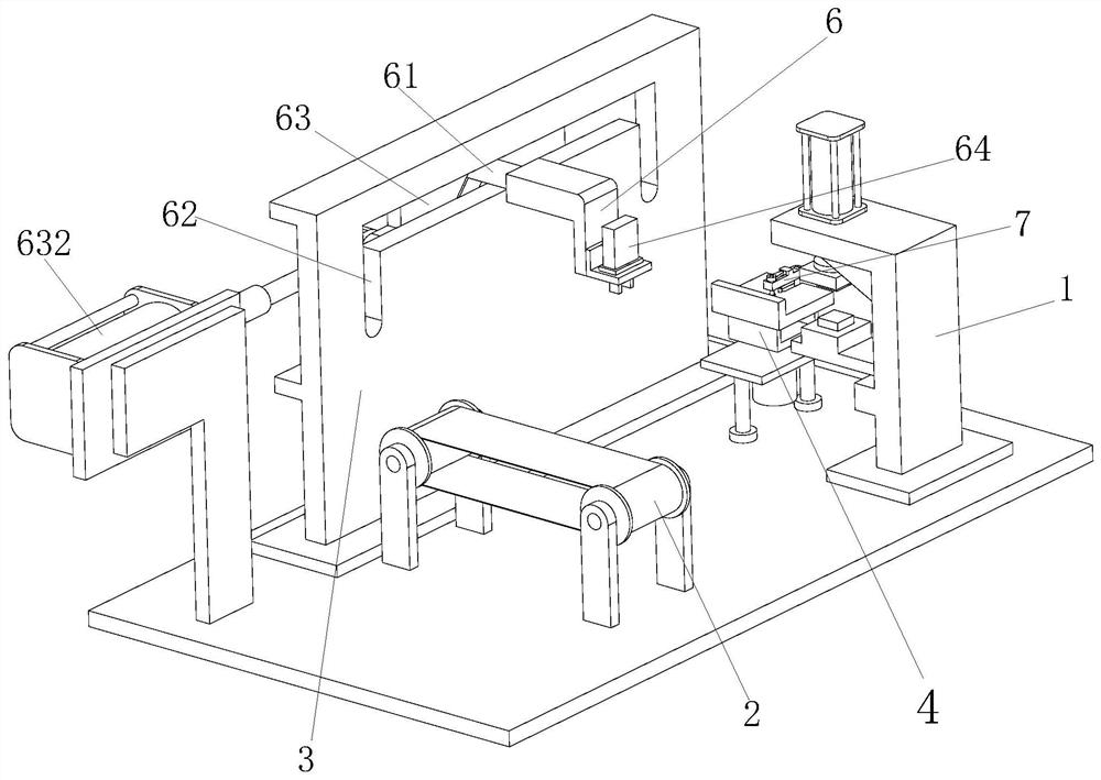
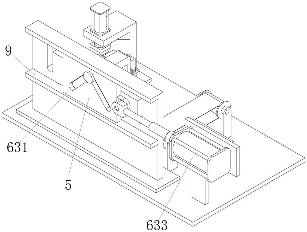
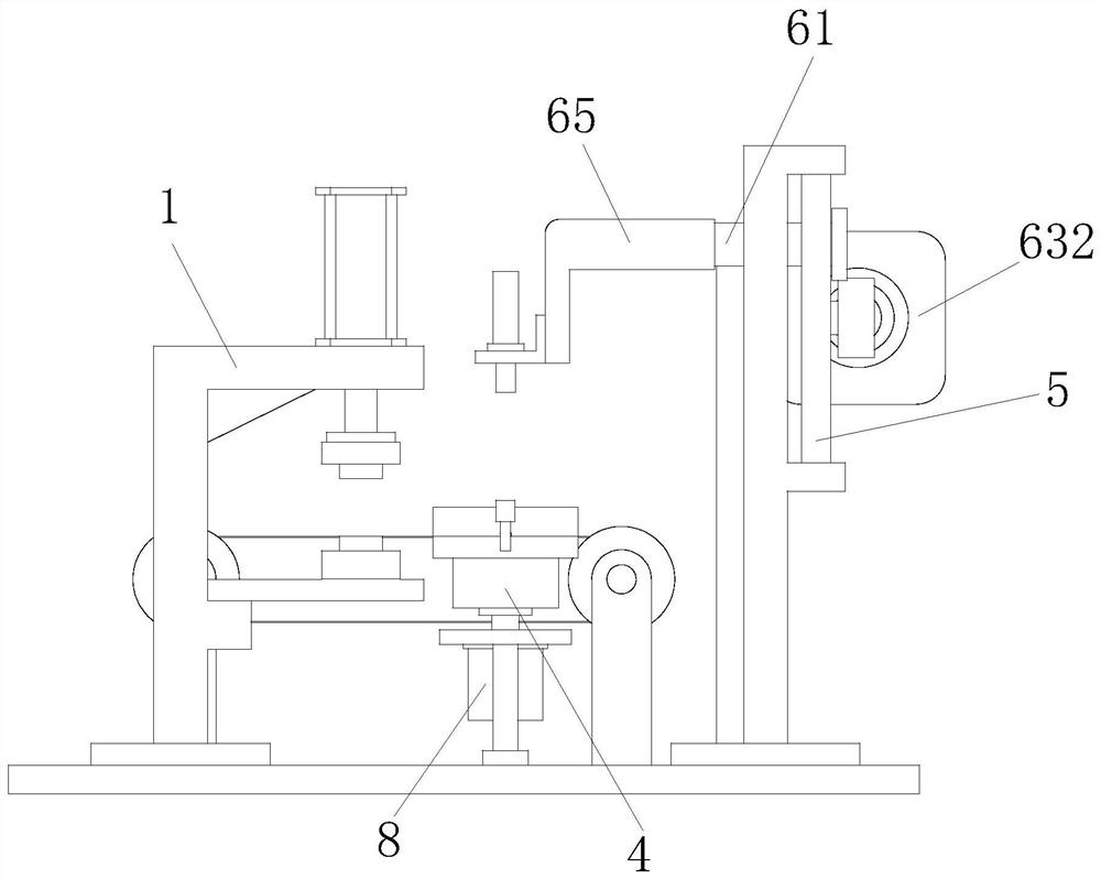
[0020] Such as Figure 1 to Figure 5 As shown, a device capable of pressure-welding copper bars for new energy vehicles includes a welding machine 1, a transmission line 2 is provided on the side of the welding machine 1, and a transmission line 2 is provided between the welding machine 1 and the transmission line 2. There is a mounting table 3, the mounting table 3, a turntable 4 that drives the copper bar into the welding machine for welding is provided between the...


PUM


Abstract

The invention relates to a device capable of performing pressure welding on a copper bar for a new energy automobile. The device comprises a welding machine, a conveying line is arranged on the side edge of the welding machine, a mounting table is arranged between the welding machine and the conveying line, a turntable for driving the copper bar to enter the welding machine for welding is arrangedbetween the mounting table and the welding machine, the turntable is connected with a motor, and a moving table is mounted on the mounting table in a sliding manner; and a grabbing device used for conveying the copper bar on the conveying line to the turntable is arranged on the moving table, and a pressing mechanism used for pressing the copper bar to prevent the copper bar from scattering is arranged on the turntable. The moving table is driven by a hydraulic cylinder to slide, so that a V-shaped groove drives a mounting rod to slide in the U-shaped groove, the copper bar is conveyed to theturntable from the conveying line, then the turntable is rotated by the motor, the copper bar is subjected to pressure welding through the welding machine, manual operation is not needed, and the automation degree is high; and a pressing rod is driven by a spring to press the copper bar, the copper bar is prevented from loosening in the rotating process, and it is guaranteed that the welding position of the copper bar is accurate.

Description

technical field [0001] The invention relates to the field of soft connection copper bar welding, in particular to a device capable of pressure-welding copper bars for new energy vehicles. Background technique [0002] Both ends of the soft connection copper bars need general pressure welding to make the connection between the copper bars stable, to prevent the copper bars from falling off and scattered in the subsequent processing process, and even cause accidents during use; the existing soft connection copper bars are pressure welded It mainly relies on manual hand-held copper bars for welding, which has a low degree of automation and high labor intensity for workers. At the same time, there are inaccurate welding positions, which leads to inaccurate welding ranges and seriously affects the yield rate of copper bars; traditional pressure welding equipment is not equipped with protective devices. It is very easy to be injured after misuse, so a device capable of pressure-we...

Claims


Application Information

Patent Timeline
Patent Type & Authority Applications(China)
IPC IPC(8): B23K20/02B23K20/26
CPCB23K20/02B23K20/26
Inventor 陶志宏
Owner WUHU HENGKUN AUTO PARTS
Why Eureka
Try Eureka