

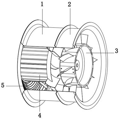
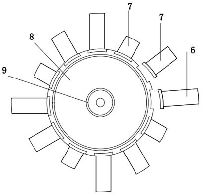
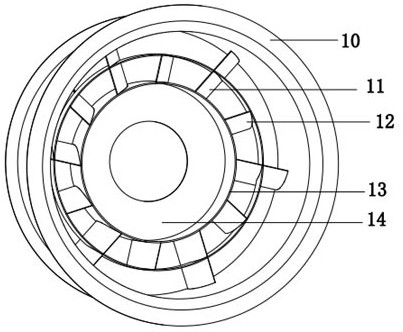
Axial flow fan with rotor blades and static front guide blades distributed in long-short staggered manner
A technology of rotor blades and staggered distribution, which is applied in the direction of axial flow pumps, electromechanical devices, mechanical equipment, etc., and can solve the problems that are not well designed with long and short staggered leading vanes and its air duct structure, performance and structure. and other issues to achieve the effect of increasing the pneumatic pressure
- Summary
- Abstract
- Description
- Claims
- Application Information
AI Technical Summary
Problems solved by technology
Method used
Image

Examples
Embodiment Construction
[0027] The following will clearly and completely describe the technical solutions in the embodiments of the present invention with reference to the accompanying drawings in the embodiments of the present invention. Obviously, the described embodiments are only some, not all, embodiments of the present invention. It should be noted that, in the description of the present invention, unless otherwise specified, the meaning of "plurality" is two or more; the terms "front", "rear", "inner", "outer", "front ", "rear end" and other indicated orientations or positional relationships are based on the orientations or positional relationships shown in the drawings, which are only for the convenience of describing the present invention and simplifying the description, rather than indicating or implying that the referred device or element must have a specific orientation, are constructed and operate in a particular orientation and therefore are not to be construed as limiting the invention....
PUM
 Abstract
Description
Claims
Application Information