
Printer interface detection device

An interface detection and printer technology, applied in mechanical measuring devices, measuring devices, mechanical devices, etc., can solve problems such as inconvenient operation, lack of rapid detection device for printer interface size, and incomplete detection functions, so as to facilitate collection and unified processing Effect

Pending Publication Date: 2021-02-09
衡阳和乐办公设备有限公司
View PDF10 Cites 0 Cited by
  • Summary
  • Abstract
  • Description
  • Claims
  • Application Information

AI Technical Summary

Problems solved by technology

After the printer interface is produced, it is necessary to detect the interface to check whether the product is qualified. When the printer interface is detected, it is especially important to detect the size of the interface and the ability to withstand pressure. China's public authorized invention CN108593431A discloses a printer ribbon interface that is resistant to tension Force detection device, which uses a motor to drive the transmission of a series of mechanical structures such as screw rods, so that the pressure plate can perform a pressure test on the printer interface and use the tank to collect debris. However, the pressure measurement structure of the device is too complicated and inconvenient to operate. The control requires very high technology, and the demand for high-tech talents is high, so it is not easy to use and promote. At the same time, the device lacks a fast detection device for the size of the printer interface, which makes the detection function incomplete. Therefore, a printer interface detection method is proposed. device

Method used


Image

  • Printer interface detection device
  • Printer interface detection device
  • Printer interface detection device

Examples


Embodiment 1

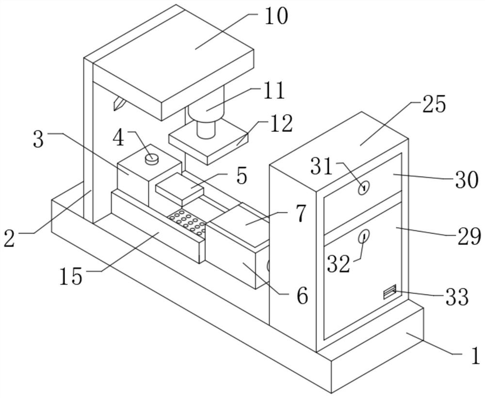
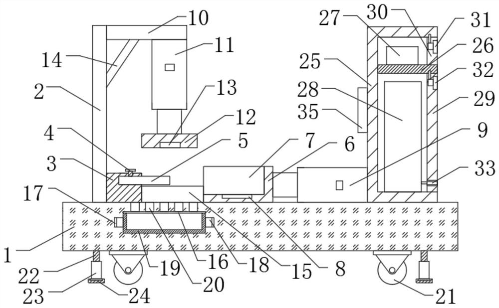
[0029] see Figure 1-5 , the present invention provides a technical solution: a printer interface detection device, including a working platform 1, the upper surface of the working platform 1 is respectively welded with a first plate body 2, a base 3, a first hydraulic cylinder 9 and a box body 25, the base 3 One side is plugged with a plug 5, the top of the base 3 is threadedly connected with a fixing bolt 4, the bottom of the fixing bolt 4 is in close contact with the top of the plug 5, the top of the first board 2 is welded with a second board 10, the second board The bottom of the body 10 is threadedly connected with a second hydraulic cylinder 11, the piston rod of the second hydraulic cylinder 11 is fixedly connected with a pressure plate 12, the inside of the pressure plate 12 is equipped with a second pressure sensor 13, and the piston rod of the first hydraulic cylinder 9 is fixedly connected with a The first housing 6, the bottom of the first housing 6 is equipped wi...

Embodiment 2

[0033] The present invention also provides an embodiment different from the first embodiment, which is different from the first embodiment:

[0034] The electrical output end of the USB charging port 33 is electrically connected to the electrical input end of the storage battery 28, the electrical output end of the storage battery 28 is electrically connected to the electrical input end of the switch group 35, and the electrical output end of the switch group 35 is connected to the electrical input end of the switch group 35. The electrical input terminals of the PLC board 27 are electrically connected, and the electrical output terminals of the PLC board 27 are respectively connected to the electrical input terminals of the first hydraulic cylinder 9, the first pressure sensor 8, the second hydraulic cylinder 11 and the second pressure sensor 13 Electrically connected, the signal transmission end of the PLC board 27 is respectively connected to the signal transmission end of t...


PUM


Abstract

The invention discloses a printer interface detection device, which comprises a working platform; a first plate body, a base, a first hydraulic cylinder and a box body are welded to the upper surfaceof the working platform, a plug is inserted into one side of the base, the top of the base is in threaded connection with a fixing bolt, and the bottom of the fixing bolt is tightly attached to the top of the plug; a second plate body is welded to the top of the first plate body. The plug is inserted into the printing interface, then the printing interface is placed into the first shell, whether the size of the printing interface is qualified or not can be rapidly detected, the printing interface is pressed to enable the first pressure sensor to be subjected to pressure induction, and the PLCboard can automatically start the first hydraulic cylinder to push the printing interface to be combined with the plug; and then the PLC board starts a second hydraulic cylinder to push a pressing plate, a second pressure sensor is used in cooperation to conduct pressure testing on the printing interface, a through hole is used in cooperation with a second shell, chippings can be conveniently collected, and unified treatment is facilitated.

Description

technical field [0001] The invention relates to the technical field of printer interface detection, in particular to a printer interface detection device. Background technique [0002] As we all know, a printer is one of the output devices of a computer, which is used to print computer processing results on related media. There are three indicators to measure the quality of a printer: printing resolution, printing speed and noise. There are many types of printers. According to whether the printing element hits the paper, it can be divided into impact printers and non-impact printers. According to the structure of printing characters, it can be divided into full-size character printers and dot-matrix character printers. According to the way a line of characters is formed on paper, it can be divided into serial printers and line printers. According to the technology adopted, it is divided into printers such as cylindrical, spherical, inkjet, thermal, laser, electrostatic, m...

Claims


Application Information

Patent Timeline
Patent Type & Authority Applications(China)
IPC IPC(8): G01N3/12G01N3/02G01B5/00
CPCG01N3/12G01N3/02G01B5/00G01N2203/0003G01N2203/0019G01N2203/0048
Inventor 王翔何艳萍蒋海建
Owner 衡阳和乐办公设备有限公司
Learn More