
Beam splitting prism group, camera assembly and electronic equipment

A technology of beam splitting prism group and camera assembly, applied in prisms, optical elements, optics, etc., can solve problems such as the decrease of light energy utilization rate, achieve the effect of increasing utilization rate and improving imaging quality

Active Publication Date: 2021-02-09
GUANGDONG OPPO MOBILE TELECOMM CORP LTD
View PDF7 Cites 0 Cited by
  • Summary
  • Abstract
  • Description
  • Claims
  • Application Information

AI Technical Summary

Problems solved by technology

Since the above scheme uses CFA to filter white light, two colors of light are filtered out on each pixel, resulting in a decrease in the utilization rate of light energy.

Method used


Image

  • Beam splitting prism group, camera assembly and electronic equipment
  • Beam splitting prism group, camera assembly and electronic equipment
  • Beam splitting prism group, camera assembly and electronic equipment

Examples


Embodiment Construction

[0026] Example embodiments will now be described more fully with reference to the accompanying drawings. Example embodiments may, however, be embodied in many forms and should not be construed as limited to the embodiments set forth herein; rather, these embodiments are provided so that this disclosure will be thorough and complete, and will fully convey the concept of example embodiments to those skilled in the art. The same reference numerals in the drawings denote the same or similar structures, and thus their detailed descriptions will be omitted.

[0027] Although relative terms such as "upper" and "lower" are used in this specification to describe the relative relationship of one component of an icon to another component, these terms are used in this specification only for convenience, for example, according to the description in the accompanying drawings directions for the example described above. It will be appreciated that if the illustrated device is turned over so...


PUM

PropertyMeasurementUnit
Thicknessaaaaaaaaaa
Thicknessaaaaaaaaaa
Thicknessaaaaaaaaaa

Abstract

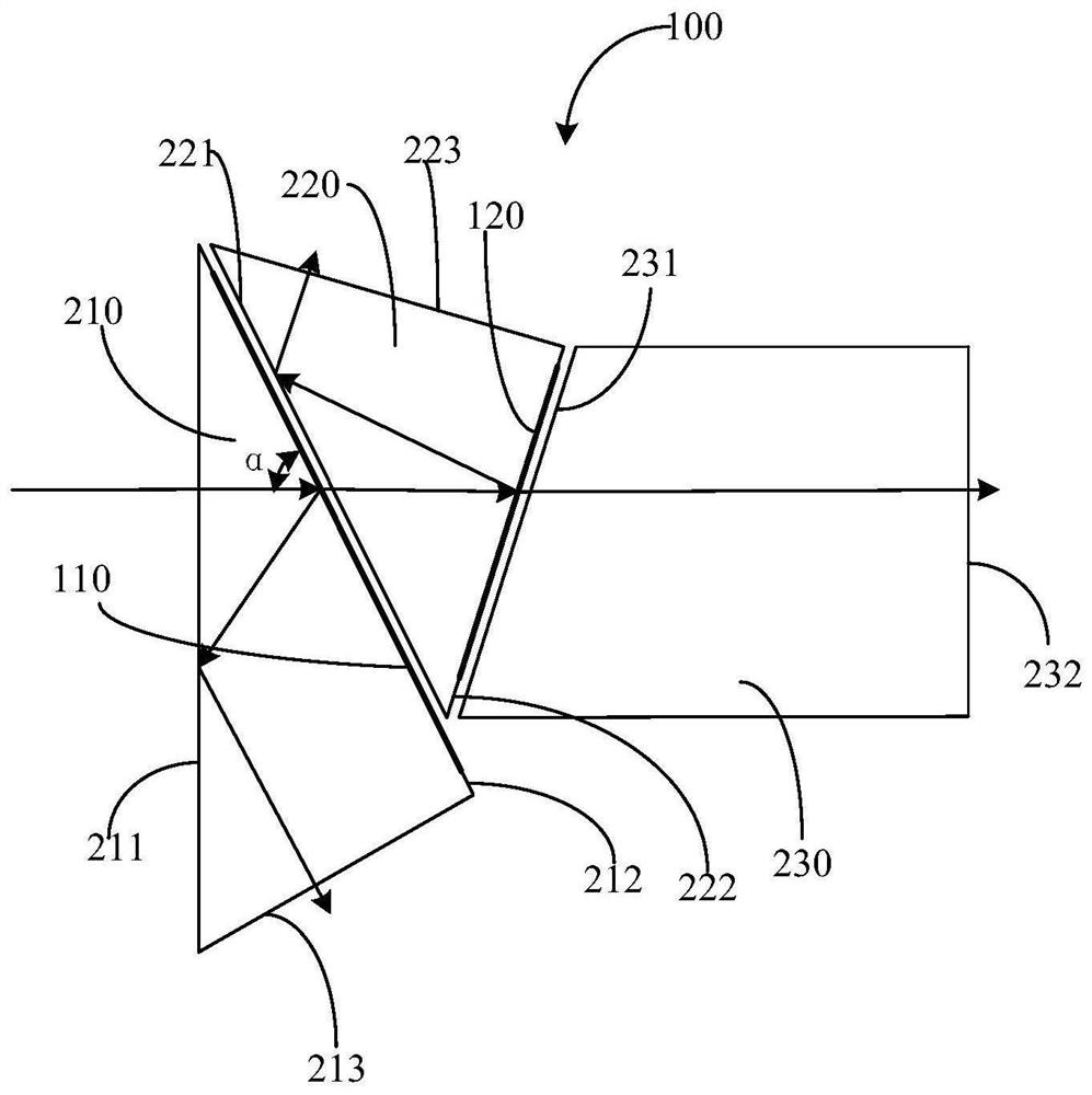
The invention belongs to the technical field of electronic equipment, and particularly relates to a beam splitting prism group, a camera assembly and electronic equipment. The beam splitting prism group comprises a first beam splitting prism, a second beam splitting prism, a third beam splitting prism, a first beam splitting film and a second beam splitting film; the first beam splitting film is arranged on one side, far away from the light incoming side, of the first beam splitting prism, and is used for reflecting light of a first waveband and transmitting light of a second waveband and a third waveband; the second beam splitter prism is arranged on one side, away from the first beam splitter prism, of the first beam splitter film; the second beam splitting film is arranged on one side,far away from the first beam splitting prism, of the second beam splitting prism; the second light splitting film is used for reflecting the light of the second waveband and transmitting the light ofthe third waveband; and the third light splitting prism is arranged on one side, far away from the second light splitting prism, of the second light splitting film. The utilization rate of light energy during shooting can be improved.

Description

technical field [0001] The present disclosure relates to the technical field of electronic equipment, in particular, to a beam splitting prism group, a camera assembly and electronic equipment. Background technique [0002] At present, for camera devices that shoot color images, since the photosensitive element can only detect the brightness (gray value) of light, a color filter array (CFA, Color Filter Array) is set on the photosensitive element in the image sensor. The CFA is mainly composed of red Green and blue (RGB, Red Green Blue) filters of three colors, a color filter is set on each pixel block of the photosensitive element, when the camera starts to capture images, the white light is directly irradiated on the CFA in the image sensor , the filtered red light, green light and blue light are irradiated on the photosensitive element, so that each pixel block records the gray value of a color light, and then interpolates according to the gray value of the reflected ligh...

Claims


Application Information

Patent Timeline
IPC IPC(8): G02B5/04G02B5/00
CPCG02B5/04G02B5/00
Inventor 谭耀成陈嘉伟韦怡
Owner GUANGDONG OPPO MOBILE TELECOMM CORP LTD
Learn More