Micro-grid control method, computer equipment, storage medium and micro-grid system
A control method and microgrid technology, applied in electrical components, circuit devices, AC network circuits, etc., can solve problems such as packet loss and microgrid control deviation, and achieve the effect of saving network resources and reducing data transmission.
- Summary
- Abstract
- Description
- Claims
- Application Information
AI Technical Summary
Problems solved by technology
Method used
Image

Examples
Embodiment Construction
[0023] In order to make the object, technical solution and advantages of the present invention clearer, the present invention will be further described in detail below in conjunction with the accompanying drawings and embodiments. It should be understood that the specific embodiments described here are only used to explain the present invention, not to limit the present invention.
[0024] It can be understood that the terms "first", "second" and the like used in the present application may be used to describe various elements herein, but unless otherwise specified, these elements are not limited by these terms. These terms are only used to distinguish one element from another element. For example, a first xx script could be termed a second xx script, and, similarly, a second xx script could be termed a first xx script, without departing from the scope of the present application.
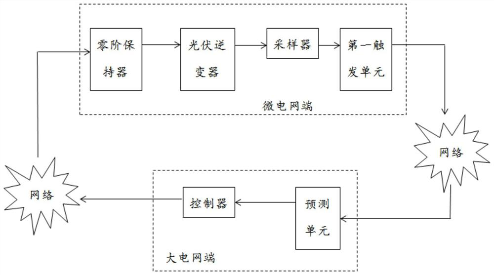
[0025] figure 1 A schematic structural diagram of a microgrid system provided by an embodiment...
PUM
 Abstract
Description
Claims
Application Information
PatSnap Eureka turns technology decisions into work you can execute. Powered by our Innovation Knowledge Graph, it runs expert workflows across engineering, life sciences, materials and intellectual property. Get your review-ready output in minutes.


