Gas compressing device special for gas power generation

A technology of compressor and gas power generation, which is applied to pump devices, components of pumping devices for elastic fluids, liquid fuel engines, etc., and can solve the problems affecting the boosting effect of compressor devices, the interference between blades and rectifiers, and the large vibration of compressor devices. and other problems, to achieve the effect of simple structure, elimination of mutual interference, and improvement of supercharging efficiency

Inactive Publication Date: 2021-02-12
娄加建
View PDF0 Cites 0 Cited by
  • Summary
  • Abstract
  • Description
  • Claims
  • Application Information

AI Technical Summary

Problems solved by technology

[0003] In order to improve the combustion efficiency of gas, it is necessary to pressurize the transported gas to increase the pressure of the whole gas, but the efficiency of the existing compressor is low, and the vibration of the whole compressor is relatively large during operation, so it is easy to cause the blades to be affected by the vibration. produce cracks;
[0004] Existing air compressors usually connect the blades with the rectifier to maintain the balance of the air pressure inside the entire device. However, after a long working time, there will be some interference between the blades and the rectifier, which will affect the boosting effect of the entire compressor.

Method used


Image

  • Gas compressing device special for gas power generation
  • Gas compressing device special for gas power generation
  • Gas compressing device special for gas power generation

Examples


Embodiment Construction

[0028] The following will clearly and completely describe the technical solutions in the embodiments of the present invention with reference to the accompanying drawings in the embodiments of the present invention. Obviously, the described embodiments are only some, not all, embodiments of the present invention. Based on the embodiments of the present invention, all other embodiments obtained by persons of ordinary skill in the art without making creative efforts belong to the protection scope of the present invention.

[0029] In the description of the invention, it should be noted that the terms "upper", "lower", "inner", "outer", "front end", "rear end", "both ends", "one end", "another end" etc. The indicated orientation or positional relationship is based on the orientation or positional relationship shown in the drawings, and is only for the convenience of describing the invention and simplifying the description, rather than indicating or implying that the referred device...


PUM


Abstract

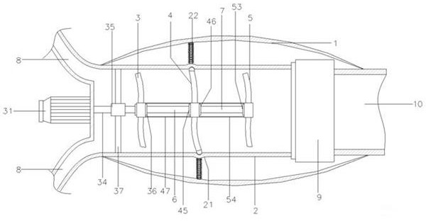
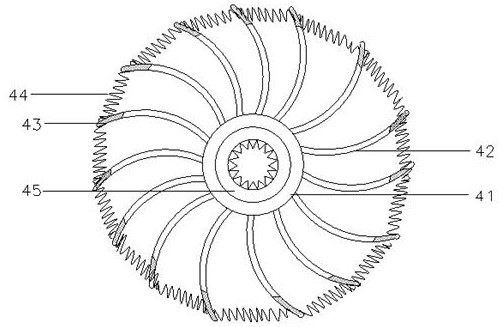
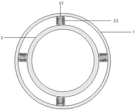
The invention discloses a gas compressing device special for gas power generation. The gas compressing device comprises a protective shell, a pressurizing cavity is arranged in the protective shell, adriving impeller, a balance impeller and a conveying impeller are sequentially arranged in the pressurizing cavity, the driving impeller is connected with the balance impeller through a first guide rod, the balance impeller is connected with the conveying impeller through a second guide rod, air inlet pipelines are arranged at the upper end and the lower end of the front side of the pressurizingcavity, a driving motor is arranged on the outer wall of the center of the front side of the pressurizing cavity and connected with the driving impeller, and a diffuser is arranged on the rear side ofthe pressurizing cavity, corresponds to the conveying impeller and is connected with an air outlet pipe. The gas compressing device is simple in structure and novel in design, the driving impeller, the balance impeller and the conveying impeller are connected with one another to replace a traditional connecting structure of the impeller and a flow regulating device, so that mutual interference caused by unstable gas pressure between the blades and the flow regulating device is effectively eradicated, and the pressurizing efficiency of the whole air compressing device is effectively improved.

Description

technical field [0001] The invention relates to the technical field of thermal power generation, in particular to a special compressor for gas-fired power generation. Background technique [0002] With the development and application of natural gas resources, the use of gas-fired generator sets will gradually increase in my country's power system, and the role of gas-fired power generation in my country's power industry will gradually increase; its working principle is to transport gas to thermal power generation devices for combustion In the cavity, the heat generated by the full combustion of gas is used to convert heat energy into mechanical energy to achieve the purpose of power generation; [0003] In order to improve the combustion efficiency of gas, it is necessary to pressurize the transported gas to increase the pressure of the whole gas, but the efficiency of the existing compressor is low, and the vibration of the whole compressor is relatively large during operati...

Claims


Application Information

Patent Timeline
Patent Type & Authority Applications(China)
IPC IPC(8): F04D19/02F04D25/06F04D29/66F04D29/32F04D29/38F04D29/059
CPCF04D19/02F04D25/06F04D29/059F04D29/321F04D29/324F04D29/662F04D29/668
Inventor 娄加建
Owner 娄加建
Why Eureka
Try Eureka