A Calibration Method of Line Laser and Manipulator

A calibration method and robotic arm technology, applied in the direction of using optical devices, instruments, measuring devices, etc., can solve the problems of unfavorable rapid calibration and strict use conditions, and achieve the effect of reliable calibration results, high degree of automation, and easy search.

Active Publication Date: 2022-06-21
TONGJI UNIV
View PDF9 Cites 0 Cited by
  • Summary
  • Abstract
  • Description
  • Claims
  • Application Information

AI Technical Summary

Problems solved by technology

[0004] Chinese invention patent CN111272102A introduces a line laser scanning three-dimensional measurement calibration method, which realizes fast line laser scanning calibration without changing the posture of the calibration plate, which can effectively reduce the calibration process and calculation complexity, but this type of method is vulnerable to The influence of the actual on-site light intensity, the use conditions in the industrial site are relatively strict, which is not conducive to rapid calibration

Method used


Image

  • A Calibration Method of Line Laser and Manipulator
  • A Calibration Method of Line Laser and Manipulator
  • A Calibration Method of Line Laser and Manipulator

Examples


Embodiment

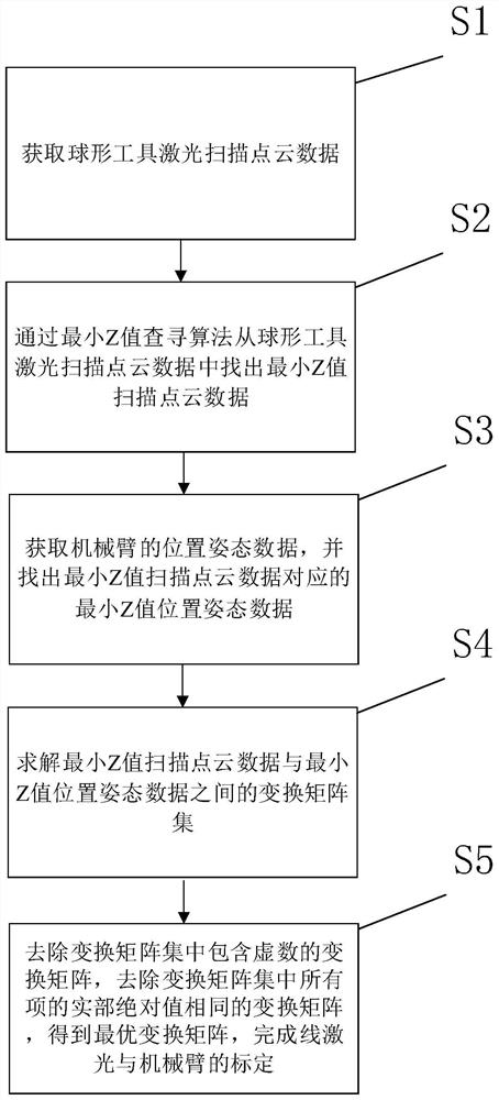
[0038] This embodiment provides a method for quickly calibrating a line laser and a robotic arm based on a spherical tool, such as figure 1 As shown, the method includes the following steps:

[0039] Step S1: obtaining point cloud data of spherical tool laser scanning;

[0040] Step S2: find out the minimum Z value scanning point cloud data from the spherical tool laser scanning point cloud data through the minimum Z value search algorithm;

[0041] Step S3: obtaining the position and attitude data of the robotic arm, and finding out the minimum Z-value position and attitude data corresponding to the minimum Z-value scanning point cloud data;

[0042] Step S4: Solve the transformation matrix set between the scan point cloud data with the minimum Z value and the position and attitude data with the minimum Z value

[0043] Step S5: Remove the set of transformation matrices transformation matrix containing imaginary numbers, remove the set of transformation matrices The t...


PUM


Abstract

The invention relates to a method for calibrating a line laser and a mechanical arm, comprising the following steps: acquiring point cloud data of a spherical tool laser scanning; and finding the minimum Z value scanning point cloud data from the spherical tool laser scanning point cloud data through a minimum Z value search algorithm ; Obtain the position and attitude data of the robotic arm, and find out the minimum Z value position and attitude data corresponding to the minimum Z value scanning point cloud data; solve the transformation matrix set between the minimum Z value scanning point cloud data and the minimum Z value position and attitude data to remove The transformation matrix set contains the imaginary number transformation matrix, and the transformation matrix with the same absolute value of the real part of all items in the transformation matrix set is removed, and the optimal transformation matrix is ​​obtained to complete the calibration of the line laser and the manipulator. Compared with the prior art, the method has the advantages of low cost, high degree of automation in the whole process, simple operation and reliable calibration results, and can meet the requirements of actual on-site use.

Description

technical field [0001] The invention relates to the field of mechanical arm and machine vision motion control, in particular to a method for calibrating a line laser and a mechanical arm. Background technique [0002] Line laser scanning imaging is a non-contact active 3D imaging method. Its working principle is to emit a line of laser light to the target object, and the camera detects the reflection information of the laser light on the object through a fixed angle, and then determines by the principle of triangulation. Height and width information of the object surface. It has the characteristics of fast scanning speed, high imaging accuracy and convenient measurement process, and is widely used in industrial field target detection, topography reconstruction and feature matching. [0003] The calibration of the line laser is often closely related to the process of data acquisition, sampling, matching and reconstruction of the 3D model of the target body, especially in som...

Claims


Application Information

Patent Timeline
Patent Type & Authority Patents(China)
IPC IPC(8): G01B11/00
CPCG01B11/002
Inventor 张剑马启航徐立云张云瞻章珈豪
Owner TONGJI UNIV
Why Eureka
Try Eureka