
Multifunctional wiring clamp

A wiring pliers, multi-functional technology, applied in the direction of connection, line/collector parts, electrical components, etc., can solve the problem of inconvenient cable connection

Active Publication Date: 2021-02-12
STATE GRID SHANDONG ELECTRIC POWER CO BOXING POWER SUPPLY CO
View PDF5 Cites 0 Cited by
  • Summary
  • Abstract
  • Description
  • Claims
  • Application Information

AI Technical Summary

Problems solved by technology

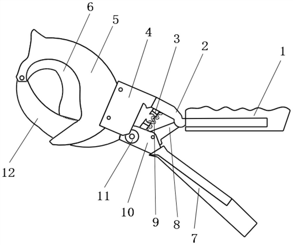
[0005] In order to solve the above-mentioned problem of inconvenient cable connection, the present invention provides a multifunctional wiring pliers, comprising an upper handle and a lower handle, the end of the upper handle is provided with an upper connecting rod, and the upper connecting rod is fixed There is a connecting plate, an upper blade is installed on the connecting plate, a lower connecting rod is arranged at the end of the lower handle, a lower blade is installed on the lower connecting rod, the head of the lower blade is connected with the upper The head of the blade is hinged; the upper connecting rod is also provided with an upper pressing assembly, the lower connecting rod is also provided with a lower pressing assembly, and a driving assembly is connected between the upper connecting rod and the lower connecting rod, A drive control assembly is installed on the upper link or the lower link, and the drive control assembly can be connected with the upper press assembly or the lower press assembly by pressing the drive control assembly, and the drive assembly can drive the upper press assembly or the lower press assembly. The line assembly is lifted; there is also a reset assembly connected between the upper link and the lower link; the upper blade has a curved upper edge, and the upper edge includes multiple segments with different curvatures and radii. Curved lower edge on the lower blade

Method used


Image

  • Multifunctional wiring clamp

Examples


Embodiment Construction

[0016] In order to make the purpose, features and advantages of the present invention more obvious and understandable, the technical solutions in the present invention will be clearly and completely described below in conjunction with the accompanying drawings in this specific embodiment. Obviously, the implementation described below Examples are only some embodiments of the present invention, but not all embodiments. Based on the embodiments in this patent, all other embodiments obtained by persons of ordinary skill in the art without creative efforts fall within the protection scope of this patent.

[0017] Such as figure 1 As shown, this specific embodiment provides a kind of multi-functional wiring pliers, which mainly includes an upper handle 1 and a lower handle 7, the end of the upper handle 1 is provided with an upper connecting rod 2, and the upper connecting rod 2 A connecting plate 4 is fixed on the top, an upper blade 5 is installed on the connecting plate 4, a lo...


PUM


Abstract

The invention relates to a multifunctional wiring clamp. According to the technical scheme, the multifunctional wiring clamp comprises an upper grab handle and a lower grab handle, an upper connectingrod is arranged at the end of the upper grab handle, a connecting plate is fixed to the upper connecting rod, an upper blade is installed on the connecting plate, a lower connecting rod is arranged at the end of the lower grab handle, and a lower blade is installed on the lower connecting rod. The head of the lower blade is hinged with the head of the upper blade; by holding and pressing the upper grab handle and the lower grab handle, a cutting hole formed between the upper blade and the lower blade can be gradually reduced, the upper blade is provided with edge sections with different curvatures and radiuses, the upper blade adapts to a cable in the process of reducing the cutting hole, and the effect of cutting the cable more easily is achieved; by operating the driving control assembly, when a cable needs to be jointed, the driving assembly is connected with the upper cable pressing assembly or the lower cable pressing assembly, the upper cable pressing assembly and the lower cable pressing assembly can be driven to gradually get close to each other by pressing the grab handle, and then a cable pressing opening is formed to achieve the cable pressing function.

Description

technical field [0001] The invention relates to the field of cable wiring devices, in particular to a multifunctional wiring clamp. Background technique [0002] At present, when connecting cables, it is generally necessary to cut and join the cables. [0003] However, when wiring a large number of cables, it takes a lot of labor and time. The existing wiring tools generally use cable scissors and splicing pliers. This way brings great inconvenience to wiring. [0004] Therefore, aiming at the present situation that cable wiring is inconvenient at present, it is an urgent problem to be solved to develop a kind of multifunctional wiring pliers. Contents of the invention [0005] In order to solve the above-mentioned problem of inconvenient cable connection, the present invention provides a multifunctional wiring pliers, comprising an upper handle and a lower handle, the end of the upper handle is provided with an upper connecting rod, and the upper connecting rod is fixed...

Claims


Application Information

Patent Timeline
IPC IPC(8): H01R43/042
CPCH01R43/0421
Inventor 崔凤霞邱斌曹金京李娟张肖肖孙海辉曹宁宁潘猛
Owner STATE GRID SHANDONG ELECTRIC POWER CO BOXING POWER SUPPLY CO
Learn More