A water supply tank with self-cleaning function

A water supply tank and self-cleaning technology, applied in the water supply main pipeline, water supply pipeline system, cleaning hollow objects, etc., can solve the problems of high water consumption, inconvenient replacement of filter element and filter plate, affecting experience, etc., to improve cleaning and maintenance. Efficiency and the effect of reducing maintenance difficulty

Active Publication Date: 2022-03-15
杭州沃德水泵制造有限公司
View PDF0 Cites 0 Cited by
  • Summary
  • Abstract
  • Description
  • Claims
  • Application Information

AI Technical Summary

Problems solved by technology

[0004] The purpose of the present invention is: in order to solve the need to stop the water supply network, and inject medicine in the water tank to sterilize or enter the water tank through the manhole for scraping, the water supply will be cut off when cleaning the water supply tank, which will affect the user experience, and After using the medicine, the inner wall of the water tank needs to be washed repeatedly, which consumes a lot of water. At the same time, it is inconvenient to replace the filter element and filter plate in the water supply tank. A self-cleaning function of the water supply tank is proposed.

Method used


Image

  • A water supply tank with self-cleaning function
  • A water supply tank with self-cleaning function
  • A water supply tank with self-cleaning function

Examples


Embodiment 1

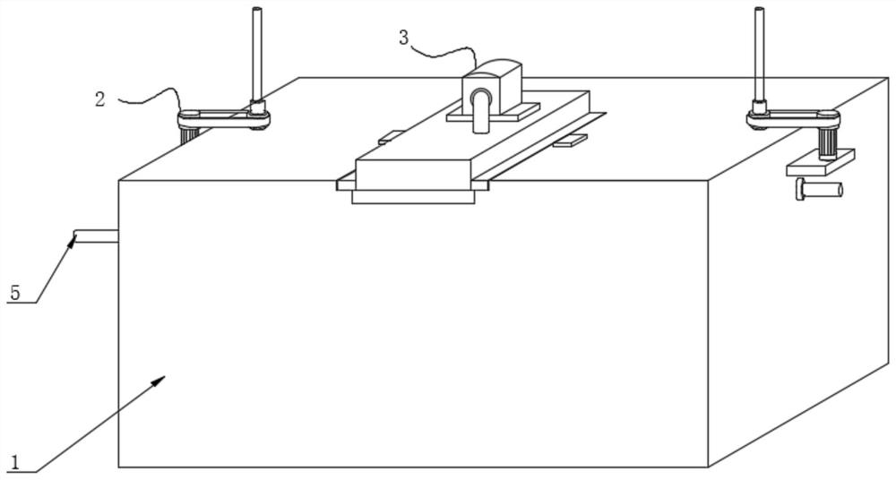
[0026] see Figure 1-6 , the present invention provides a technical solution: a water supply tank with self-cleaning function, including a water tank body 1, a filter mechanism 3 slidingly connected to the top of the water tank body 1, a water storage mechanism 4 in the inner cavity of the water tank body 1, and a water tank body 1 There are cleaning mechanisms 2 on both sides of the body;

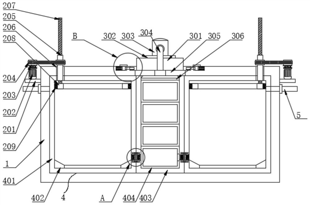
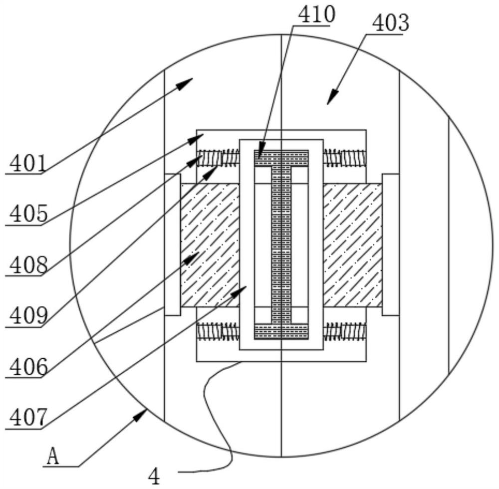
[0027] The water storage mechanism 4 includes two water diversion tanks 401 and a movable seat 403, the two sides of the movable seat 403 are respectively attached to the opposite surfaces of the two water diversion tanks 401, the inner cavity of the movable seat 403 is placed with a filter holder 404, and the inner cavity of the movable seat 403 Both sides and one side of the water diversion tank 401 are connected with a telescopic tube 406, and the other end of the telescopic tube 406 is connected with a limit seat 407, and the limit seat 407 is located in the groove 405 provided on both...

Embodiment 2

[0030] refer to Figure 7-8, the filter mechanism 3 includes a water pump 303, the bottom of the water pump 303 is fixedly connected with a mounting plate 302, the bottom of the mounting plate 302 is fixedly connected with a mounting seat 301, both sides of the mounting seat 301 are fixedly connected with a block 307, and one side of the block 307 is provided with a card The hole 308 is connected with a sliding rod 309 in the clamping hole 308, the outer wall of the sliding rod 309 is slidably connected with a sliding sleeve 310, one end of the sliding rod 309 is fixedly connected with a slider 311, and the corresponding positions on both sides of the top of the water tank body 1 are provided with chute 312, the slider 311 is slidably connected in the chute 312, the sliding sleeve 310 is embedded on one side of the slider 311, the side of the slider 311 is fixedly connected with the first spring 312, and the other end of the first spring 312 is connected to the inner cavity of ...

Embodiment 3

[0033] On the basis of Embodiment 1, the cleaning mechanism 2 includes a scraper 208, the scraper 208 is slidably connected to the inner cavity of the water separator 401, the top side of the scraper 208 is fixedly connected with a threaded post 207, and the outer wall of the threaded post 207 is threaded with a Threaded cylinder 205, the outer wall of the threaded cylinder 205 is provided with a bearing 206, and the bearing 206 is embedded in the water tank body 1 and the side of the water diversion tank 401, the outer wall of the threaded cylinder 205 is provided with a driven wheel, and the driven wheel is driven by a belt 204 Connected with a drive wheel 203, the bottom of the drive wheel 203 is fixedly connected with a motor 202, and the motor 202 is arranged on one side of the water tank body 1, and the outer wall of the scraper 208 is fixedly connected with a brushing brush 209, and the brushing brush 209 is connected with the water tank The inner cavities of 401 are fit...


PUM


Abstract

The invention discloses a water supply tank with self-cleaning function, which belongs to the technical field of water supply tanks, and comprises a water tank body, the top of the water tank body is slidably connected with a filtering mechanism, the inner cavity of the water tank body is provided with a water storage mechanism, and the water tank body Both sides of the main body are equipped with a cleaning mechanism, the filter mechanism includes a water pump, the bottom of the water pump is fixedly connected with a mounting plate, the bottom of the mounting plate is fixedly connected with a mounting seat, and both sides of the mounting seat are fixedly connected with blocks , a card hole is opened on one side of the card block. In the present invention, the bacterial water liquid is quickly discharged through the designed connecting pipe, thereby satisfying the cleaning effect of the water diversion tank, and the water diversion tank on both sides can clean the water diversion tank on one side independently, so that the water diversion tank on the other side The cabinet works normally, and the water liquid in the water distribution tank on the cleaning side can be filtered by the filter element frame when it is attracted by negative pressure, so as to ensure the cleanliness of the water supply in the water distribution tank on the normal side, thereby effectively avoiding the interruption of water supply caused by the cleaning work.

Description

technical field [0001] The invention belongs to the technical field of water supply tanks, in particular to a water supply tank with self-cleaning function. Background technique [0002] In the design of water supply projects, water supply tanks are often used as the peak regulation water storage equipment of the water supply system. In order to ensure that the water supply can still be carried out for a certain period of time when the water supply is cut off, the water supply tanks are often installed in the newly built communities to reduce the risk of water cutoffs. It can ensure the safety of water supply and relieve the pressure of supply and demand of the water network. It has gradually become an indispensable measure in the water supply system. However, due to the long-term accumulation of water in the water tank, microorganisms in the water tank are easily adsorbed on the inner wall of the water tank through breeding and reproduction, and need to be cleaned. [0003]...

Claims


Application Information

Patent Timeline
Patent Type & Authority Patents(China)
IPC IPC(8): E03B11/00E03B7/09B08B9/087B01D35/00B01D29/96
CPCE03B11/00E03B7/09B01D29/96B01D35/00B08B9/087
Inventor 田育民
Owner 杭州沃德水泵制造有限公司
Why Eureka
Try Eureka