Burr cleaning method for chamfering position of plastic bottle forming die

A technology for forming molds and cleaning methods, which is applied in the direction of manufacturing tools, accessories of toolholders, and tools for lathes, etc., can solve problems such as manual deburring, achieve the effects of reducing labor intensity, ensuring cleaning effects, and improving processing efficiency

Active Publication Date: 2017-06-13
浙江利盛包装科技有限公司
View PDF10 Cites 0 Cited by
  • Summary
  • Abstract
  • Description
  • Claims
  • Application Information

AI Technical Summary

Problems solved by technology

[0004] The present invention intends to provide a method for cleaning burrs at the chamfers of plastic bottle forming molds to solve the problem of manual removal of burrs after the chamfering is completed

Method used


Image

  • Burr cleaning method for chamfering position of plastic bottle forming die
  • Burr cleaning method for chamfering position of plastic bottle forming die

Examples


Embodiment 1

[0028] (1) Install the chamfering knife and forming mold on the CNC machine tool, so that the forming mold is located directly below the chamfering knife;

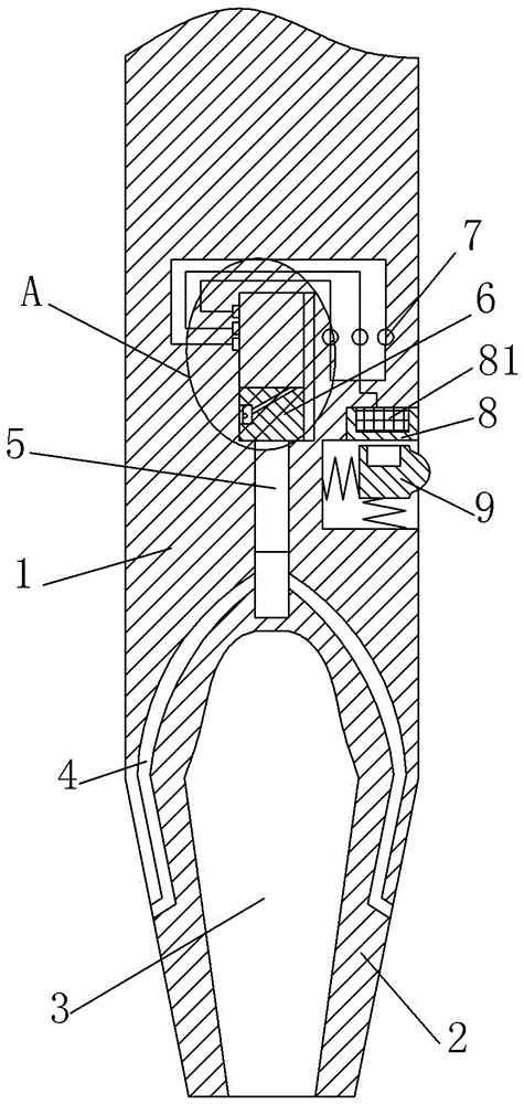
[0029] (2) Start the CNC machine tool. While driving the chamfering knife to rotate at a speed of 200r / min, the CNC machine tool drives the chamfering knife to move downward at a speed of 0.5cm / s. The chamfering knife moves downward while rotating to form The mold is chamfered. At this time, a large amount of heat will be generated on the cutting edge 2. The heat enters the air inlet hole and enters the piston cavity along the vent hole 4. The heat entering the piston cavity will act on the piston tail 5, the piston The tail part 5 will move upwards along the piston cavity under the action of the heat, and the piston tail part 5 will drive the piston head 6 to move upwards along the working chamber while moving upwards along the piston cavity;

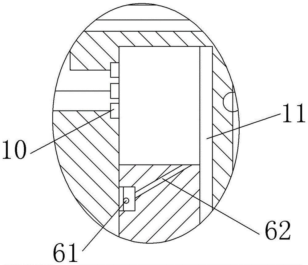
[0030] (4) Turn on the light source 61 at the installation hole. When the chamfe...

Embodiment 2

[0032] The difference between embodiment 2 and embodiment 1 is that in step (2), the rotating speed of the chamfering knife is 250r / min, and the speed of the downward movement of the chamfering knife is 1.5cm / s.

Embodiment 3

[0034] The difference between embodiment 3 and embodiment 1 is that in step (2), the rotating speed of the chamfering knife is 300r / min, and the downward moving speed of the chamfering knife is 3cm / s.

[0035] The chamfering knife used in each of the above-mentioned embodiments includes a chamfering knife body 1, on which two mounting parts are arranged, each mounting part is provided with a cutting edge 2, and a cutting edge 2 is arranged on each mounting part, A flute 3 is provided between the blades 2 .

[0036] Each cutting edge 2 is provided with an air intake hole, a piston chamber is provided on the upper side of the chip removal groove 3, and a vent hole 4 is respectively opened on both sides of the piston chamber, and one side of the vent hole 4 communicates with the piston chamber , the other side of the ventilation hole 4 communicates with the carrying hole, and a working chamber is also arranged on the upper side of the piston chamber, and a lens 11 is arranged on ...


PUM


Abstract

The invention discloses a burr cleaning method for chamfering position of a plastic bottle forming die. A chamfer mill adopted for the method comprises a chamfer mill body, the chamfer mill body is provided with at least two cutting edges, and the chamfer mill body is provided with a work cavity; the side wall of the work cavity is provided with a lens, the work cavity is furthermore internally provided with a piston, the piston is provided with a light through hole and an installation hole, and the installation hole is provided with a light source; the side wall of the work cavity is furthermore provided with optoelectronic switches, and the optoelectronic switches are electrically connected with alternating-current power sources; the chamfer mill body is furthermore provided with an installation cavity, the installation cavity is internally provided with a circular-arc-shaped protruded block, a first spring is connected between the circular-arc-shaped protruded block and the work cavity, the circular-arc-shaped protruded block is provided with a permanent magnet and a circular arc edge, the upper side of the circular-arc-shaped protruded block is furthermore provided with an electromagnetic block, and the electromagnetic block is sleeved with a magnet exciting coil. By means of the burr cleaning method, the problem that manual deburring is needed after chamfering is completed in a traditional machining manner is solved, the machining efficiency of the forming die is effectively improved, and labor intensity of workers is lowered.

Description

technical field [0001] The invention relates to a method for cleaning burrs at chamfered corners. Background technique [0002] Recently, plastic products have become popular as bottles for beverages, etc. At present, plastic bottles are mostly produced by extrusion-blow molding, that is, the resin is plasticized and melted by an extruder to form a tubular blank, and then the blank is placed Put it into the forming mold, blow it with compressed air, and after cooling and shaping, a plastic bottle with the same shape as the inner cavity of the mold will be obtained. [0003] In the production process of plastic bottles, the quality of the molding mold has a great influence on the molding quality of the plastic bottle. Generally, the sharp corners of the surface of the mold need to be chamfered after the molding mold is completed, so as to avoid the mold on the mold. The sharp corners affect the appearance of the plastic bottle. At present, the chamfering of the forming mold ...

Claims


Application Information

Patent Timeline
Patent Type & Authority Applications(China)
IPC IPC(8): B23D79/00B23B27/00
CPCB23B27/00B23D79/00
Inventor 程地英
Owner 浙江利盛包装科技有限公司
Why Eureka
Try Eureka