Prying-resistant magnetic door lock control system

A control system and magnetic force technology, applied in the field of magnetic door lock control system, can solve the problems of waste of electric energy, damaged door lock, large electric energy damage, etc., and achieve the effect of high destruction intensity

Pending Publication Date: 2021-02-19
HUBEI UNIV OF SCI & TECH
View PDF0 Cites 0 Cited by
  • Summary
  • Abstract
  • Description
  • Claims
  • Application Information

AI Technical Summary

Problems solved by technology

[0003] However, no matter the existing electromagnetic lock is located indoors or the silicon steel sheet is located indoors, there is a risk of being pried open, that is to say, destroying the coil part or the silicon steel sheet in the electromagnetic structure can make the electromagnetic adsorption structure invalid, thereby achieving The purpose of the damaged door lock; moreover, the existing magnetic door lock is completely dependent on electromagnetic force, which has high requirements on the size of the magnetic field, and the damage to the electric energy is relatively large; finally, the normal power-on state of the existing magnetic door lock is the locked state , requires a continuous supply of electric energy, which also causes a waste of electric energy, and the lock will be unlocked when the power is turned off, which poses a greater safety hazard

Method used


Image

  • Prying-resistant magnetic door lock control system

Examples


Embodiment Construction

[0012] The following are specific embodiments of the present invention and in conjunction with the accompanying drawings, the technical solutions of the present invention are further described, but the present invention is not limited to these embodiments.

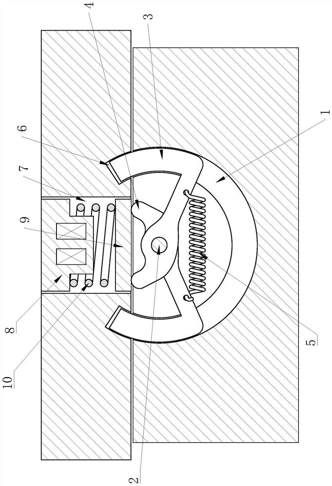
[0013] Such as figure 1 As shown, it includes a locking mechanism arranged on the door frame and an electromagnetic structure arranged on the door body. The locking mechanism includes an arc-shaped guide groove 1 set on the door frame, and two swing arms are symmetrically arranged in the guide groove 1. A pin shaft 2 is fixedly arranged at the center of the guide groove 1. The middle part of the swing arm is hinged on the pin shaft 2. The swing arm includes a latch 3 at one end of the hinge point and a pressure block 4 at the other end of the hinge point. The two swing arms There is a spring column 5 in a stretched state connected between them, and two sockets 6 corresponding to the two latches 3 are opened on the door bod...


PUM


Abstract

The invention provides a prying-resistant magnetic door lock control system, and belongs to the technical field of electric power control. The system comprises a locking mechanism and an electromagnetic structure. The locking mechanism comprises an arc-shaped guide groove formed in a door frame; two swing arms are symmetrically arranged in the guide groove; a pin shaft is fixedly arranged in the center of the guide groove; the middles of the swing arms are hinged to the pin shaft, and each swing arm comprises a bolt located at one end of a hinge point and a pressing block located at the otherend of the hinge point; a spring column in a stretched state is connected between the two swing arms; and two inserting holes corresponding to the two bolts respectively are formed in a door body. Theelectromagnetic structure comprises a mounting hole formed in the door body, an armature block is fixedly arranged in the mounting hole, an electrified coil is winded on the armature block, a pressing plate is slidably connected to the end, close to the door frame, of the mounting hole, the pressing block can abut against the pressing plate, and a return spring in a compressed state is connectedbetween the pressing plate and the armature block. The prying-resistant magnetic door lock control system has the advantages of high prying resistance and the like.

Description

technical field [0001] The invention belongs to the technical field of electric power control, and relates to a tamper-proof magnetic force door lock control system. Background technique [0002] Magnetic door locks are also called electromagnetic locks. Using the principle of electromagnetism, when the current passes through the silicon steel sheet, the electromagnetic lock will generate a strong suction force to tightly absorb the adsorption iron plate to achieve the effect of locking the door. As long as a small current electromagnetic lock will generate a huge magnetic force, the access control system that controls the power supply of the electromagnetic lock will cut off the power after identifying the correct person, and the electromagnetic lock will open the door when it loses its suction. [0003] However, no matter the existing electromagnetic lock is located indoors or the silicon steel sheet is located indoors, there is a risk of being pried open, that is to say, ...

Claims


Application Information

Patent Timeline
Patent Type & Authority Applications(China)
IPC IPC(8): E05B47/06E05B63/10E05B15/10
CPCE05B15/10E05B15/101E05B47/0002E05B47/06E05B63/10
Inventor 吴敏常果邹亮
Owner HUBEI UNIV OF SCI & TECH
Why Eureka
Try Eureka