Air humidifier automatically controlled by PLC

An air humidifier and humidifier technology, applied in air humidification systems, heating methods, lighting and heating equipment, etc., can solve problems such as troublesome operation, poor atomization effect, lack of convenience, etc., and achieve increased range and good effect. Effect

Inactive Publication Date: 2021-02-19
XIAN LANXIN IND AUTOMATION ENG CO LTD
View PDF1 Cites 0 Cited by
  • Summary
  • Abstract
  • Description
  • Claims
  • Application Information

AI Technical Summary

Problems solved by technology

With the development of economy and society and the improvement of people's living standards, air humidifiers with reliable functions and good purification effects are more and more popular. Traditional air humidifiers are mainly composed of water tanks and humidifier bodies, and the atomization effect is not good. Well, and there is no automatic control system, it is troublesome to operate. According to a PLC automatic control air humidifier published by China Patent Network CN108344091A, although the degree of automation is increased, the operation is more convenient, but it can only be operated in one direction. Humidification, unable to adjust the angle of the humidifier, lack of convenience

Method used


Image

  • Air humidifier automatically controlled by PLC
  • Air humidifier automatically controlled by PLC
  • Air humidifier automatically controlled by PLC

Examples


Embodiment 1

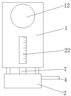
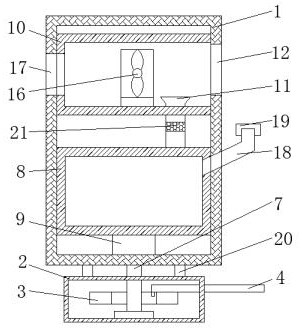
[0023] Example 1 as Figure 1-2 As shown, a PLC automatic control air humidifier is characterized in that it includes a humidifier body 1, a base 2 is provided at the bottom of the humidifier body 1, a ratchet 3 is provided inside the base 2, and a ratchet 3 is movably connected above the ratchet 3. The movable rod 4, the side of the movable rod 4 close to the ratchet 3 is movably connected with a push block 5, the push block 5 matches the ratchet 3, a limiting mechanism is provided between the ratchet 3 and the movable rod 4, and the axis of the ratchet 3 passes through the connecting rod 6 is connected with a rotating rod 7, the top of the rotating rod 7 runs through the base 2 and is fixedly connected with the humidifier body 1, the interior of the humidifier body 1 is fixedly connected with a water tank 8, and the bottom end of the water tank 8 is fixedly connected with an atomizer 9, humidifying The inside of the device body 1 and above the water tank 8 are fixedly connec...

Embodiment 2

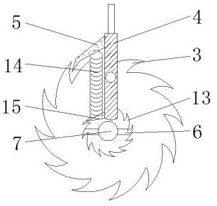
[0024] Embodiment 2 is on the basis of embodiment 1 such as image 3 As shown, the limiting mechanism includes a ratchet groove 13, a spring 14 and a limiting block 15. The ratchet 3 has a ratchet groove 13 inside, and the bottom end of the pushing block 5 is connected with a limiting block 15 through a spring 14. The limiting block 15 matches the ratchet groove 13. .

Embodiment 3

[0025] Embodiment 3 is such as on the basis of embodiment 1 figure 2 As shown, the blowing mechanism includes a fan 16 and an air inlet 17 , the fan 16 is fixedly connected inside the support box 10 , and the side of the support box 10 and the humidifier body 1 away from the mist outlet 12 is provided with an air inlet 17 .


PUM


Abstract

The invention discloses an air humidifier automatically controlled by a PLC. The air humidifier comprises a humidifier body, wherein a base is arranged at the bottom end of the humidifier body; a ratchet wheel is arranged in the base; a movable rod is movably connected to the upper portion of the ratchet wheel; a pushing block is movably connected to one side of the movable rod; a limiting mechanism is arranged between the ratchet wheel and the movable rod; a rotating rod is connected to the axis of the ratchet wheel through a connecting rod; a water tank is fixedly connected to the interior of the humidifier body; an atomizer is fixedly connected to the bottom end of the water tank; a supporting box is fixedly connected to the position, located above the water tank, in the humidifier body; an atomizing pipe is fixedly connected to the top end of the water tank; an air blowing mechanism is arranged in the supporting box; and a mist outlet is formed in one side of the humidifier body. The air humidifier has the beneficial effects that the air humidifying angle can be adjusted, the air humidifying range is enlarged, and the air humidifying effect is better.

Description

technical field [0001] The invention relates to the field of air humidifiers, in particular to an air humidifier automatically controlled by PLC. Background technique [0002] An air humidifier is a device for maintaining indoor air humidity. It mainly atomizes water into ultrafine particles and blows the water mist to the outside through a fan to increase the humidity of the environment. With the development of economy and society and the improvement of people's living standards, air humidifiers with reliable functions and good purification effects are more and more popular. Traditional air humidifiers are mainly composed of water tanks and humidifier bodies, and the atomization effect is not good. Well, and there is no automatic control system, it is troublesome to operate. According to a PLC automatic control air humidifier published by China Patent Network CN108344091A, although the degree of automation is increased, the operation is more convenient, but it can only be o...

Claims


Application Information

Patent Timeline
Patent Type & Authority Applications(China)
IPC IPC(8): F24F6/12F24F13/00F24F13/28F24F13/32
CPCF24F6/12F24F13/00F24F13/28F24F13/32
Inventor 鲍成辉
Owner XIAN LANXIN IND AUTOMATION ENG CO LTD
Why Eureka
Try Eureka