Metal tube bending fatigue test device and method capable of controlling stress on line
A technology for controlling stress and testing equipment, which is applied in the direction of measuring equipment, using repeated force/pulsation force to test the strength of materials, instruments, etc., which can solve the problems of unable to automatically implement constant stress value and high equipment life, so as to reduce bending stress , high precision effect
- Summary
- Abstract
- Description
- Claims
- Application Information
AI Technical Summary
Problems solved by technology
Method used
Image

Examples
Embodiment Construction
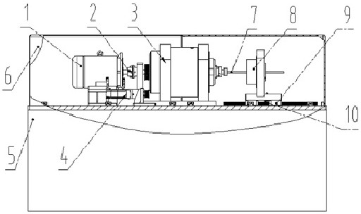
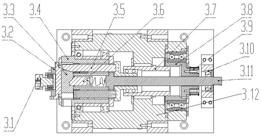
[0024] Combine below figure 1 and figure 2 The specific implementation of the metal pipe bending fatigue test device capable of controlling the magnitude of stress on-line according to the present invention will be further described.
[0025] Such as figure 1 and figure 2 Shown is the invented metal pipe bending fatigue test device that can control the stress on-line. The drive motor 1 is fixedly installed on the left side of the platform plate on the frame 5, and the output shaft end is connected with the drive shaft 3.11 through the coupling 2; the drive shaft 3.11 The middle part is supported by an auxiliary support seat 3.10, and the end is connected with the internal rotating head 3.4 of the drive eccentric part 3, so that the output end mechanism can perform high-speed rotational movement with the motor 1; a servo motor 4 is placed laterally on the central axis, and is installed and fixed on 5 on the frame platform plate is synchronously connected with the synchrono...
PUM
 Abstract
Description
Claims
Application Information
PatSnap Eureka turns technology decisions into work you can execute. Powered by our Innovation Knowledge Graph, it runs expert workflows across engineering, life sciences, materials and intellectual property. Get your review-ready output in minutes.


