Tool base of high-speed motor performance testing device

A technology for testing devices and high-speed motors, which is applied in the direction of motor generator testing, measuring devices, measuring device casings, etc., which can solve the problems of increasing the workload of engine testing, taking a long time, and the deviation of measurement data between the dynamometer and the engine.

Pending Publication Date: 2021-02-19
四川诚邦浩然测控技术有限公司
View PDF0 Cites 0 Cited by
  • Summary
  • Abstract
  • Description
  • Claims
  • Application Information

AI Technical Summary

Problems solved by technology

Due to the strong vibration during the measurement of the engine power, the measurement data of the dynamometer and the engine in the vibration environment will deviate, and in the engine performance test, not only the power test is required, but also the stall test

Method used


Image

  • Tool base of high-speed motor performance testing device
  • Tool base of high-speed motor performance testing device

Examples


Embodiment Construction

[0016] The present invention will be further described below in conjunction with the accompanying drawings, but the protection scope of the present invention is not limited to the following description.

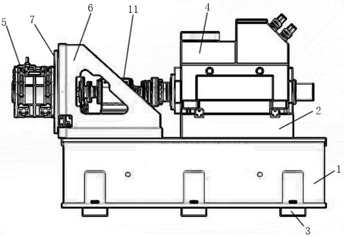
[0017] Such as figure 1 As shown, a tooling base of a high-speed motor performance testing device includes a base 1, a slide seat 2 and a fixed bracket 6 arranged on the base 1, and several linear guide rails are arranged on the top of the base 1, and the slide base 2 is connected with the base 1 through a linear guide rail, so that the sliding seat 2 can slide on the base 1. The function of the sliding seat 2 is to install the dynamometer 4. By sliding the sliding seat 2, the rotation axis of the dynamometer 4 can be realized. shaft device, etc., the fixed bracket 6 is fixed on the top of the base 1, and the fixed bracket 6 is located in the sliding direction of the sliding seat 2, the fixed bracket 6 is provided with a torque sensor, and the torque sensor and the sliding se...


PUM


Abstract

The invention relates to a tool base of a high-speed motor performance testing device. The tool base comprises a base (1), and a sliding seat (2) and a fixed bracket (6) which are arranged on the base(1), wherein a plurality of linear guide rails are arranged at the top of the base (1), the sliding seat (2) is connected with the base (1) through the linear guide rails, the fixed bracket (6) is fixed at the top of the base (1), and the fixed bracket (6) is located in the sliding direction of the sliding seat (2), a torque sensor is arranged on the fixed bracket (6), and a bearing seat (11) isarranged between the torque sensor and the sliding seat (2). According to the invention, the locked-rotor device and the mounting base of the dynamometer (4) are integrated into a whole so as to conveniently test the performance of the motor, and the centering effect of the tested motor (5) and the dynamometer (4) is monitored, so that the purpose of accurate measurement is achieved.

Description

technical field [0001] The invention relates to the field of motor performance testing, in particular to a tooling base of a high-speed motor performance testing device. Background technique [0002] The dynamometer is a device used to test the performance of the engine. When using it, it is necessary to align the engine shaft with the dynamometer, so that the power of the engine can be completely transmitted to the dynamometer, so that accurate data can be measured. . Due to the strong vibration during the measurement of the engine power, the measurement data of the dynamometer and the engine in the vibration environment will deviate, and in the engine performance test, not only the power test is required, but also the stall test is required. It takes a lot of time to transfer and re-align the engine during the test, which greatly increases the workload of the engine test. Therefore, the current process of engine performance testing is cumbersome and complicated, and the ...

Claims


Application Information

Patent Timeline
IPC IPC(8): G01R31/34G01R1/04G01L3/24G01D21/02
CPCG01D21/02G01L3/24G01R1/0408G01R31/34
Inventor 程社林隆先军张强曹诚军杨忠敏卢中永刘乐乐
Owner 四川诚邦浩然测控技术有限公司
Why Eureka
Try Eureka