Method for ascertaining and/or monitoring a mechanical state of a tie rod apparatus

A steering rod, mechanical state technology, applied in the direction of steering rod, steering mechanism, electric steering mechanism, etc., can solve problems such as a large amount of computing power, complex detection, evaluation and logical correlation of sensor characteristic variables, so as to improve performance efficiency, improve Operational safety and improved efficiency

A steering rod, mechanical state technology, applied in the direction of steering rod, steering mechanism, electric steering mechanism, etc., can solve problems such as a large amount of computing power, complex detection, evaluation and logical correlation of sensor characteristic variables, so as to improve performance efficiency, improve Operational safety and improved efficiency

CN112384431AActive Publication Date: 2021-02-19ROBERT BOSCH GMBH

Image

  • Method for ascertaining and/or monitoring a mechanical state of a tie rod apparatus
  • Method for ascertaining and/or monitoring a mechanical state of a tie rod apparatus
  • Method for ascertaining and/or monitoring a mechanical state of a tie rod apparatus

Examples


Embodiment Construction

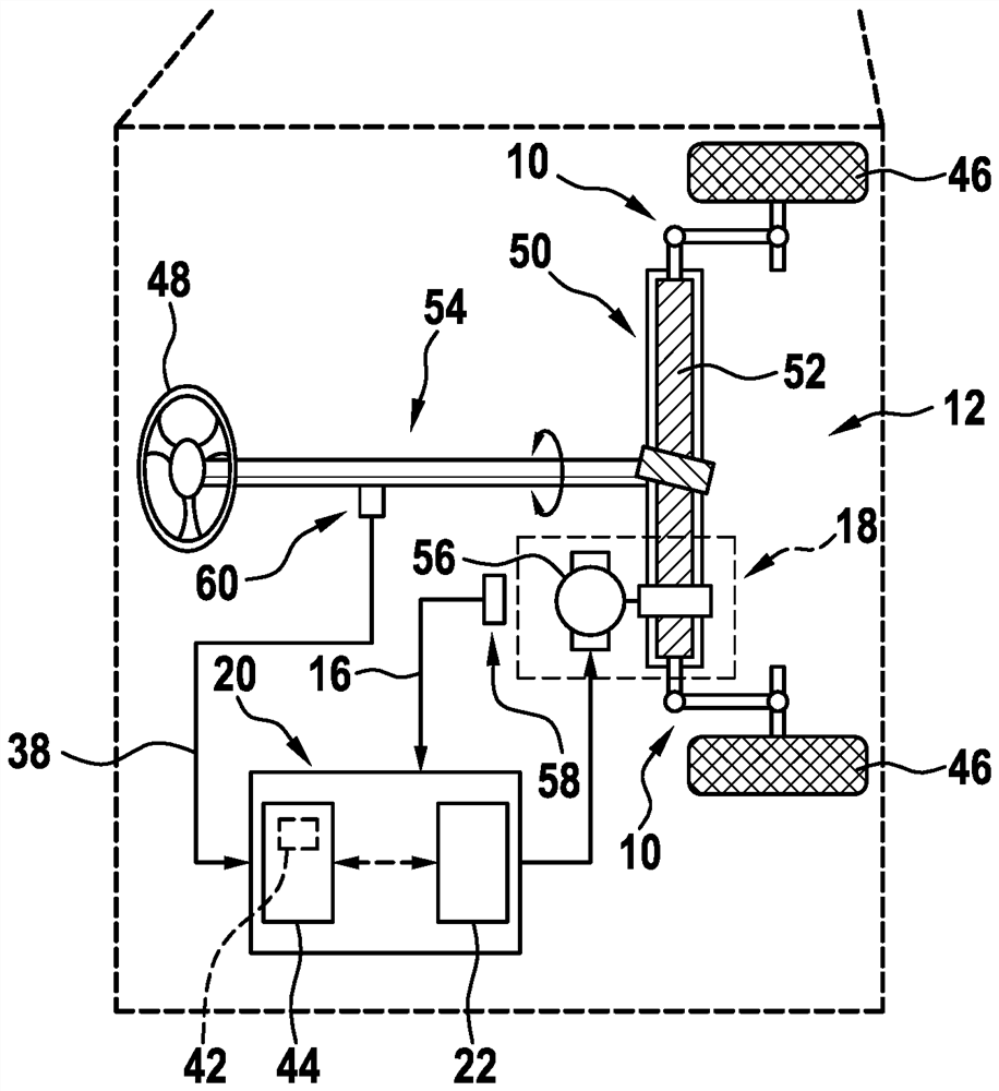
[0026] Figure 1a with 1b In a simplified illustration, a vehicle 14 , which is designed as a motor vehicle by way of example, has a plurality of wheels 46 and a steering system 12 , which is designed as a conventional steering system by way of example. Vehicle 14 may, for example, be a vehicle with partially automated, highly automated, and / or fully automated driving modes. Steering system 12 has an operative connection to wheels 46 and is designed to influence the direction of travel of vehicle 14 . Furthermore, the steering system 12 is designed as an electrically assisted steering system, and in the present case in particular has an electrically assisted steering in the form of automatic steering. In principle, however, it is also conceivable to configure the steering system as a steer-by-wire system.

[0027] Steering system 12 comprises a steering handle 48 , in the present case exemplarily configured as a steering wheel for applying a manual torque, a wheel steering ...


PUM


Abstract

The invention proposes a method for ascertaining and / or monitoring a mechanical state of at least one tie rod apparatus (10) of an electrically assisted steering system (12) of a vehicle (14), whereinat least one operating characteristic variable (16), which is correlated to a steering movement, of at least one steering actuator (18) and / or of at least one steering controller (20) of the steeringsystem (12) is ascertained and evaluated for ascertaining and / or for monitoring the mechanical state of the tie rod apparatus (10).

Description

technical field [0001] The invention relates to a method according to claim 1 for determining and / or monitoring the mechanical state of a tie rod arrangement of an electrically assisted steering system of a vehicle. [0002] Furthermore, the invention relates to a computing unit for carrying out such a method and to a vehicle comprising an electrically assisted steering system with a steering rod device, a steering actuator and a steering control device, the electrically assisted steering system Computing units for performing such methods are included. Background technique [0003] A method for determining the mechanical state of a steering system is known from DE 198 15 470 A1, wherein the determination and evaluation is made by means of sensors such as steering angle sensors, lateral acceleration sensors, yaw rate sensors or driving stability control sensor systems Compliance or exceeding of tolerances and / or defined limit values. In this case, therefore, the actual valu...

Claims


Application Information

Patent Timeline
19 Feb 2021
Publication
CN112384431A
IPC
B62D5/04; B62D7/20
CPC
B62D5/0481; B62D7/20; B62D5/0484; B62D9/00
Inventors
A·J·阿科斯塔阿庞特; T·施米德