Clutch pressing plate clamp

A clutch and pressure plate clamping technology, applied in the direction of clamping, manufacturing tools, support, etc., can solve the problems that the clutch pressure plate cannot be accurately clamped and fixed, the processing accuracy is low, and the operation is troublesome, so as to achieve convenient and simple clamping and improve processing efficiency. , Improve the effect of product processing accuracy

Inactive Publication Date: 2021-02-23
ANHUI POLYTECHNIC UNIV MECHANICAL & ELECTRICAL COLLEGE
View PDF10 Cites 0 Cited by
  • Summary
  • Abstract
  • Description
  • Claims
  • Application Information

AI Technical Summary

Problems solved by technology

The existing fixtures are cumbersome to operate, and cannot achieve accurate clamping and fixing of the clutch pressure plate, resulting in low processing accuracy of the product

Method used


Image

  • Clutch pressing plate clamp
  • Clutch pressing plate clamp
  • Clutch pressing plate clamp

Examples


Embodiment Construction

[0014] The specific embodiment of the present invention will be described in further detail by describing the embodiments below with reference to the accompanying drawings, the purpose is to help those skilled in the art to have a more complete, accurate and in-depth understanding of the concept and technical solutions of the present invention, and contribute to its implementation.

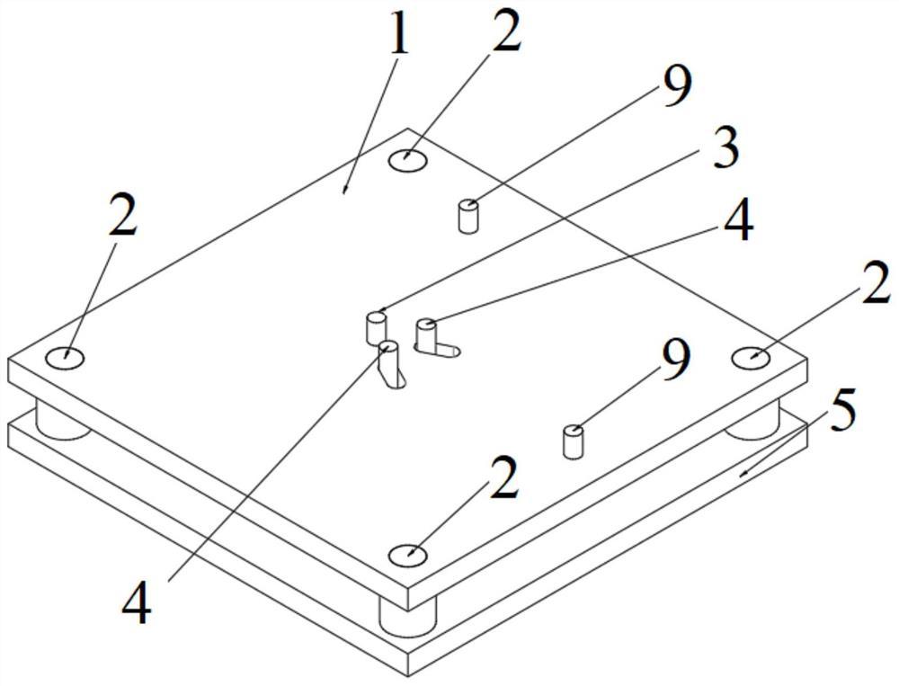
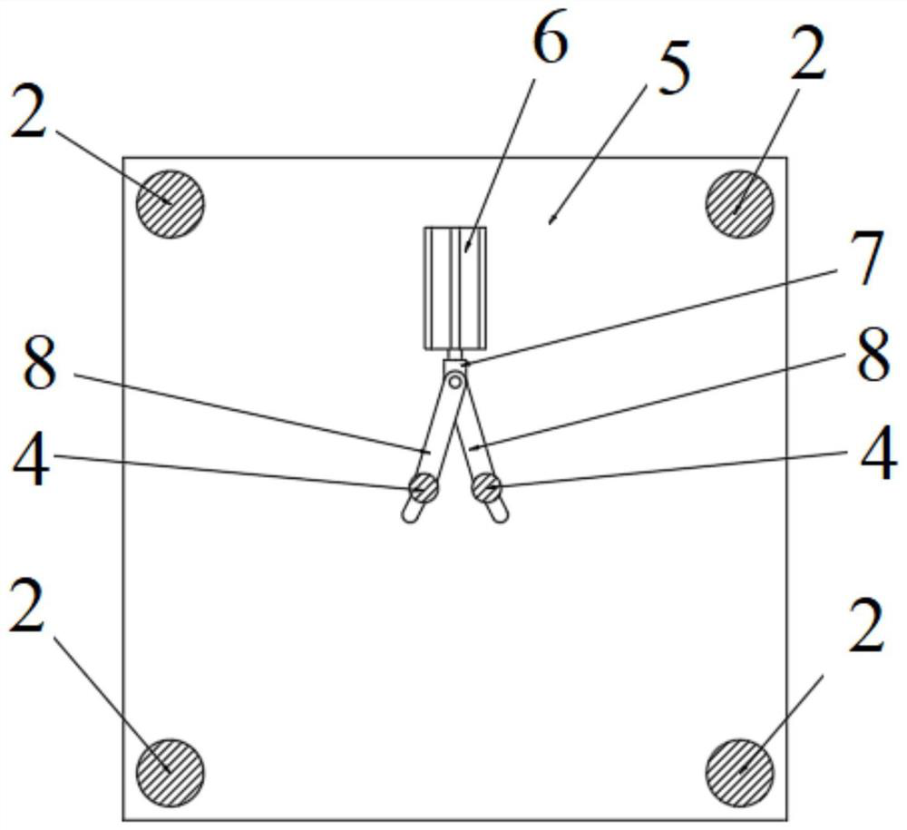
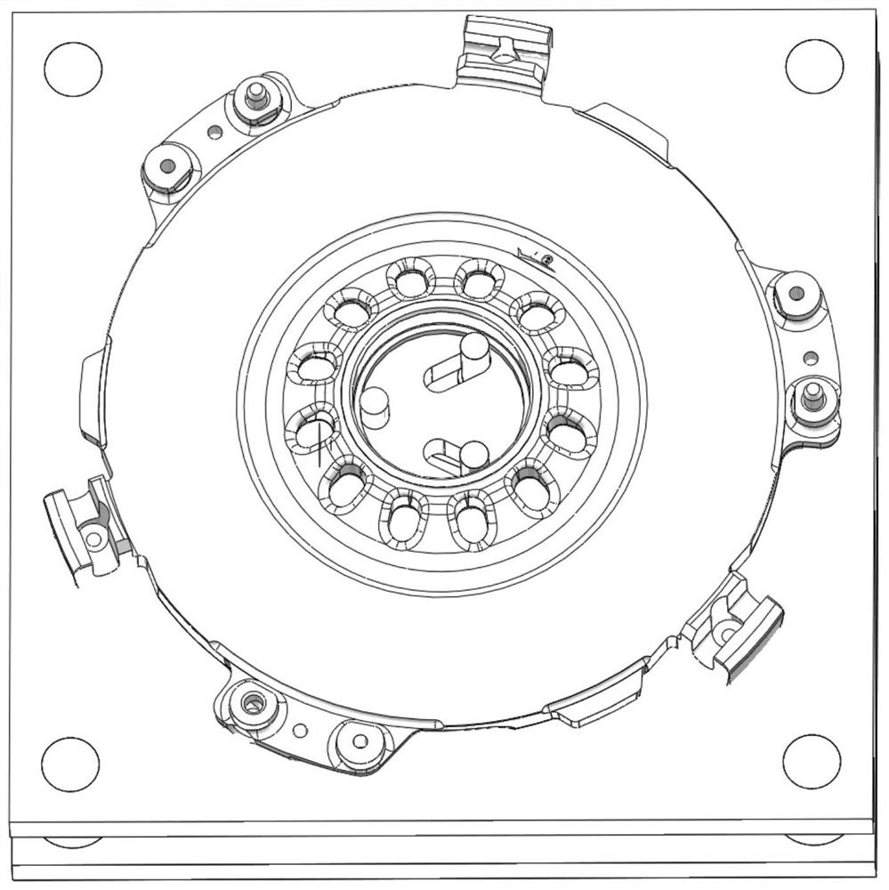
[0015] Such as Figure 1 to Figure 3 As shown, the present invention provides a clutch pressure plate clamp, including a fixed plate 5, a backing plate 1 arranged on the fixed plate 5, a first positioning pin 3 arranged on the backing plate 1 and used for positioning the clutch pressure plate and The second positioning pin 9, the two fixed columns 4 for applying the pressing force to the clutch pressure plate to fix it, and the drive that is arranged between the fixed plate 5 and the backing plate 1 and is used to control the movement of the two fixed columns 4 Mechanism, the backing plate 1 has ...


PUM


Abstract

The invention discloses a clutch pressing plate clamp. The clamp comprises a fixing plate, a base plate arranged on the fixing plate, a first positioning pin and a second positioning pin which are arranged on the base plate and used for positioning a clutch pressing plate, two fixing columns used for exerting pressing force on the clutch pressing plate to fix the clutch pressing plate as well as adriving mechanism arranged between the fixing plate and the base plate and used for controlling the two fixing columns to move; the base plate is provided with two guide holes allowing the two fixingcolumns to penetrate through; and the guide holes are kidney-shaped holes. According to the clutch pressing plate clamp, the inner circle of a workpiece is positioned through the positioning pins andthe fixing columns, the center of the workpiece can be accurately and effectively positioned, and the product machining precision can be improved; and clamping is convenient and easy, and the machining efficiency can be improved.

Description

technical field [0001] The invention belongs to the technical field of clamps, in particular, the invention relates to a clutch pressure plate clamp. Background technique [0002] As a part that transmits the output power of the engine, the clutch pressure plate needs to have high precision. During the manufacturing process of the clutch pressure plate, it needs to be fixed by a fixture and processed in a milling machine. The existing fixtures are cumbersome to clamp, and cannot realize accurate clamping and fixing of the clutch pressure plate, resulting in low processing precision of the product. Contents of the invention [0003] The present invention aims to solve at least one of the technical problems existing in the prior art. For this reason, the present invention provides a clamp for a clutch pressure plate, with the purpose of improving processing efficiency and product processing accuracy. [0004] In order to achieve the above object, the technical solution ado...

Claims


Application Information

Patent Timeline
Patent Type & Authority Applications(China)
IPC IPC(8): B23C3/00B23C9/00B23Q3/08
CPCB23C3/00B23C9/00B23Q3/08
Inventor 龚光超胡恒
Owner ANHUI POLYTECHNIC UNIV MECHANICAL & ELECTRICAL COLLEGE
Why Eureka
Try Eureka