
Convenient positioning and clamping device for new energy battery

A positioning and clamping, convenient technology, applied in the direction of workpiece clamping devices, manufacturing tools, etc., can solve the complex operation of new energy battery positioning and clamping devices, reduce the clamping efficiency of new energy batteries, and increase the difficulty of new energy positioning and clamping and other problems to achieve the effect of avoiding shaking, improving practicality and reducing difficulty

Inactive Publication Date: 2021-02-23
王刚
View PDF5 Cites 0 Cited by
  • Summary
  • Abstract
  • Description
  • Claims
  • Application Information

AI Technical Summary

Problems solved by technology

[0004] However, the existing new energy battery positioning and clamping device is complicated to operate, which increases the difficulty of new energy positioning and clamping, thereby increasing the time required for new energy battery positioning and clamping, and further reducing the clamping efficiency of new energy batteries. Thereby reducing the processing efficiency of new energy batteries

Method used


Image

  • Convenient positioning and clamping device for new energy battery
  • Convenient positioning and clamping device for new energy battery
  • Convenient positioning and clamping device for new energy battery

Examples


Embodiment Construction

[0030] The following will clearly and completely describe the technical solutions in the embodiments of the present invention with reference to the accompanying drawings in the embodiments of the present invention. Obviously, the described embodiments are only some, not all, embodiments of the present invention.

[0031] In describing the present invention, it should be understood that the terms "upper", "lower", "front", "rear", "left", "right", "top", "bottom", "inner", " The orientation or positional relationship indicated by "outside", etc. is based on the orientation or positional relationship shown in the drawings, and is only for the convenience of describing the present invention and simplifying the description, rather than indicating or implying that the referred device or element must have a specific orientation, so as to Specific orientation configurations and operations, therefore, are not to be construed as limitations on the invention.

[0032] refer to Figure ...


PUM


Abstract

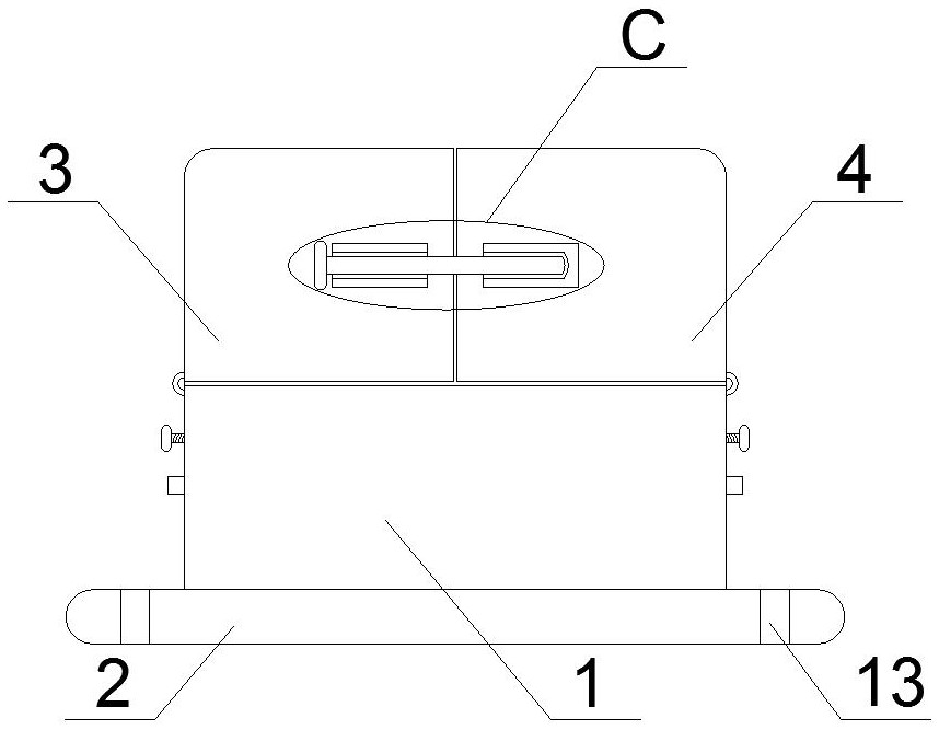
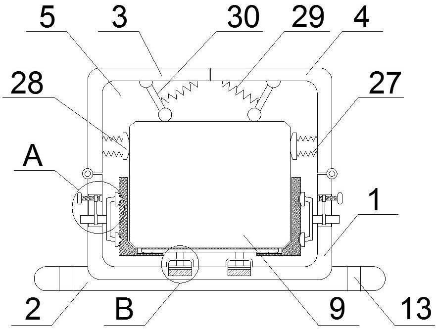
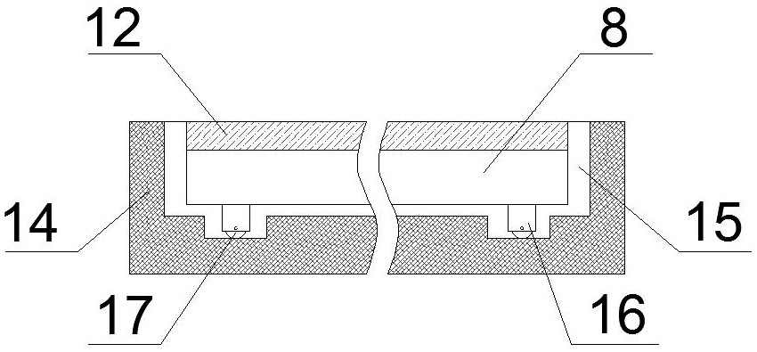
The invention discloses a convenient positioning and clamping device for a new energy battery. The convenient positioning and clamping device comprises a shell, wherein the top wall of the shell is rotationally connected with a left clamping cover and a right clamping cover through hinges; a fixing mechanism is arranged on the outer side walls of the left clamping cover and the right clamping cover; a placement groove is formed in the shell; two piston grooves are formed in the inner bottom wall of the placement groove; supporting rods are connected in the two piston grooves in a sliding manner; the top walls of the two supporting rods are fixedly connected with a supporting plate; and the two sides of the supporting plate are connected with clamping plates through sliding mechanisms. According to the convenient positioning and clamping device, a threaded rod is screwed in, a first fixing sleeve moves in a mechanism groove, at the moment, a connecting rod drives a second fixing sleeveto move, then two connecting plates are driven to move oppositely, an abutting block is pushed to abut against the clamping plates, then the two clamping plates clamp and fix a battery main body, thedifficulty of positioning and clamping the new energy battery is reduced, and therefore the time required for positioning and clamping the new energy battery is saved, and the device is simple to operate and convenient to use.

Description

technical field [0001] The invention relates to the technical field of new energy batteries, in particular to a convenient positioning and clamping device for new energy batteries. Background technique [0002] New energy (NE): also known as unconventional energy. Refers to various forms of energy other than traditional energy. Refers to energy sources that have just begun to be developed and utilized or are being actively researched and yet to be promoted, such as solar energy, geothermal energy, wind energy, ocean energy, biomass energy, and nuclear fusion energy. With the development of new energy vehicles, new energy vehicle batteries have been applied on a large scale. New energy batteries are new types of batteries that use new energy technologies to reduce "greenhouse gas" emissions and pollution. New energy vehicle batteries can be divided into two categories: categories, namely batteries and fuel cells. [0003] Lithium battery is a kind of new energy battery. It...

Claims


Application Information

Patent Timeline
Patent Type & Authority Applications(China)
IPC IPC(8): B25B11/00
CPCB25B11/00
Inventor 王刚
Owner 王刚
Learn More