Printer paper outlet structure and printer

A paper outlet, printer technology, applied in printing devices, printing and other directions, can solve the problems of electronic devices damage, entry, easy to be splashed by water, etc., to achieve the effect of increasing reliability, increasing waterproof performance, and convenient operation

Pending Publication Date: 2021-02-23
SHANGHAI SUMI TECH CO LTD +1
View PDF0 Cites 0 Cited by
  • Summary
  • Abstract
  • Description
  • Claims
  • Application Information

AI Technical Summary

Problems solved by technology

Among them, the small ticket thermal printer that is often used in the kitchen is easy to be splashed by water due to the special use scene, and the water will enter the printer from the paper outlet, causing damage to the electronic components inside the machine

Method used


Image

  • Printer paper outlet structure and printer
  • Printer paper outlet structure and printer
  • Printer paper outlet structure and printer

Examples


Embodiment 1

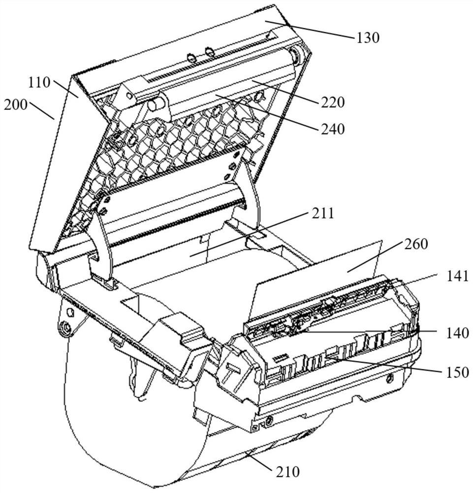
[0053] This embodiment is a printer paper outlet structure 100, such as Figure 1 to Figure 4 As shown, the paper outlet structure 100 of the printer includes: a first cover 110 , a second cover 120 , a waterproof strip 130 and an alarm device 140 .

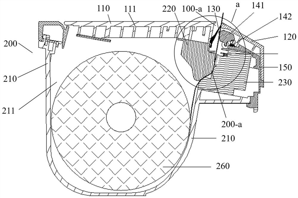
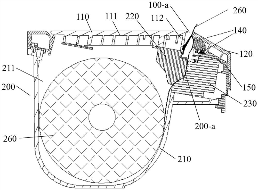
[0054] Specifically, the first machine cover 110 and the second machine cover 120 can be installed outside the printer 200, and the first machine cover 110 and the second machine cover 120 are connected to each other, leaving a gap outside the connection to form the paper outlet 100 -a. The waterproof strip 130 and the alarm device 140 are installed inside the paper outlet 100-a.

[0055] Further, the first cover 110 includes a first cover main body 111 and a waterproof strip fixing part 112, the side of the first cover main body 111 close to the second cover 120 extends in the opposite direction along the paper output direction, forming a waterproof strip fixing part 112. In the drawings of this embodiment, the outside of the...

Embodiment 2

[0071] This embodiment is a printer 200, such as Figure 1 to Figure 5 As shown, the printer 200 includes a paper bin 210, a first printer head 220, a second printer head 230, and the printer paper outlet structure 100 of the first embodiment. It should be noted that the drawings of this embodiment include the printer paper outlet structure 100 of the first embodiment and other structures, so the drawings of this embodiment can be used to explain the solution of the first embodiment. The same parts of this embodiment and Embodiment 1 will not be repeated here.

[0072] Specifically, such as Figure 5 As shown, the inside of the paper bin 210 has a printing paper storage chamber 211, and the opening edge of the printing paper storage chamber 211 is hingedly connected to the end of the first cover main body 111 away from the waterproof strip fixing part 112. The first printer head 220 is mounted on the waterproof strip fixing part 112. part 112 inside. That is, the first cove...


PUM


Abstract

The invention discloses a printer paper outlet structure and a printer. The printer paper outlet structure comprises a first machine cover, a second machine cover, a waterproof strip and an alarm device. The first machine cover comprises a first machine cover body and a waterproof strip fixing part, one end of the waterproof strip is arranged at one side of the waterproof strip fixing part, the other end of the waterproof strip can rebound to abut against one side of the second machine cover, and a paper outlet channel is formed between the alarm device and the waterproof strip. In a natural state, the waterproof strip has certain pre-pressure on the second machine cover so as to seal an paper outlet; in the paper outlet state, printing paper applies acting force in the paper outlet direction to the waterproof strip, and a paper outlet gap is formed between the waterproof strip and the second machine cover after the waterproof strip is stressed and bent; and in a paper jam state, the printing paper extrudes the alarm device to trigger paper jam alarm. The printer paper outlet structure is composed of the first machine cover, the second machine cover, the waterproof strip and the alarm device, and the purposes that the structure is simple, operation is convenient, and the waterproof performance of the printer can be effectively improved are achieved.

Description

technical field [0001] The invention relates to the technical field of printers, in particular to a printer paper outlet structure and a printer. Background technique [0002] Receipt printers are widely used in supermarkets, restaurants, kitchens and other places. Receipt printers include: dot matrix micro printers, thermal micro printers, portable micro printers and desktop micro printers. Among them, the small ticket thermal printer that is often used in the kitchen is easy to be splashed by water due to the special use scene, and the water will enter the printer from the paper outlet, causing damage to the electronic components inside the machine. [0003] Therefore, whether a printer structure can be designed to increase the waterproof performance of the printer on the basis of ensuring the printer structure is simple and easy to operate is the problem that this patent intends to solve. Contents of the invention [0004] In view of the above defects in the prior art,...

Claims


Application Information

Patent Timeline
Patent Type & Authority Applications(China)
IPC IPC(8): B41J29/13B41J29/46B41J11/00B41J2/315B41J11/66B41J11/70
CPCB41J2/315B41J11/006B41J11/663B41J11/666B41J11/703B41J29/13B41J29/46
Inventor 周勇林喆李百科陈桂鸿
Owner SHANGHAI SUMI TECH CO LTD
Why Eureka
Try Eureka