
Tubular pile steel bar framework reinforcing and bundling device

A steel skeleton and binding device technology, applied in the direction of sheet pile walls, buildings, foundation structure engineering, etc., can solve the problems of unstable fixed position of the steel cage, increase the difficulty of operation, hardness influence and other problems, and achieve the convenience of equidistant positioning welding, It is convenient for welding operation and saves the effect of handling

Active Publication Date: 2021-02-23
富强科技股份有限公司
View PDF6 Cites 0 Cited by
  • Summary
  • Abstract
  • Description
  • Claims
  • Application Information

AI Technical Summary

Problems solved by technology

[0003]The steel wire is wound and bound on the surface of the steel bar. Even if the steel bar and the steel wire are welded, the thickness of the steel wire diameter and the hardness of the steel wire itself cannot play a good role. Fixing effect, when the welded steel cage is placed for pipe piles and concrete is poured, the fixed position of the steel cage is easy to be unstable, and the hardness of the concrete after setting is affected, and the previous binding and welding operations Increased the difficulty of operation, inconvenient to use

Method used


Image

  • Tubular pile steel bar framework reinforcing and bundling device
  • Tubular pile steel bar framework reinforcing and bundling device
  • Tubular pile steel bar framework reinforcing and bundling device

Examples


Embodiment Construction

[0022] The following will clearly and completely describe the technical solutions in the embodiments of the present invention with reference to the accompanying drawings in the embodiments of the present invention. Obviously, the described embodiments are only some, not all, embodiments of the present invention. Based on the embodiments of the present invention, all other embodiments obtained by persons of ordinary skill in the art without making creative efforts belong to the protection scope of the present invention.

[0023] In the description of the present invention, it should be noted that the terms "center", "upper" and "lower"

[0024] The orientation or positional relationship indicated by "left", "right", "vertical", "horizontal", "inner", "outer", etc. is based on the orientation or positional relationship shown in the drawings, and is only for the convenience of describing the present invention and simplified descriptions, rather than indicating or implying that th...


PUM


Abstract

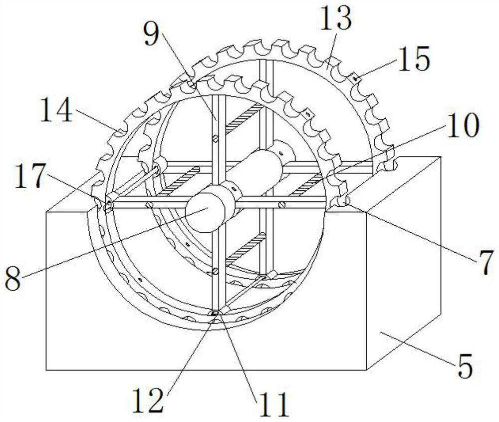
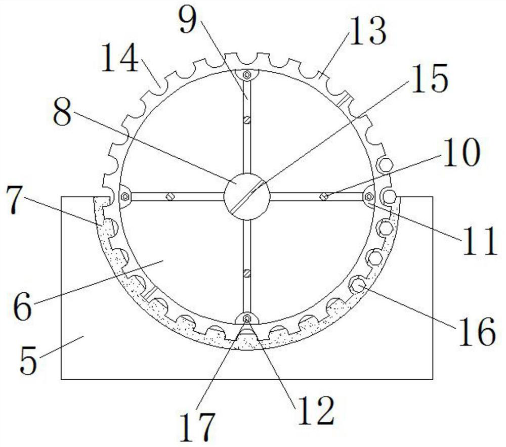
The invention discloses a tubular pile steel bar framework reinforcing and bundling device, and relates to the technical field of tubular pile steel bar bundling. The tubular pile steel bar frameworkreinforcing and bundling device comprises a base; a sliding groove is formed in the top of the base; a fixed base is arranged at the top of the base; a motor is installed at the top of the fixed base;a fixed disc is arranged on one side of the motor; a limiting disc is fixed in the fixed disc; a plurality of sets of limiting holes are formed in the outer side of the limiting disc; and a connecting shaft is fixed to one side of the limiting disc. By means of correspondence of limiting grooves and steel bar rings and correspondence of upper notches in the steel bar rings and the limiting holes,steel bars can be placed in the upper notches, the limiting disc and the steel bar rings are driven to rotate through rotation of the fixed disc, the steel bars can be conveniently placed on the surfaces of the steel bar rings, and then the steel bars are welded at the positions of the upper notches; and the strength of a steel bar framework is improved through the steel bar rings, the steel bars, first connecting steel bars, second connecting steel bars, reinforcing steel bars, upper reinforcing steel bar rings and lower reinforcing steel bar rings.

Description

technical field [0001] The invention relates to the technical field of pipe pile steel bar binding, in particular to a pipe pile steel bar skeleton reinforcement binding device. Background technique [0002] Pipe piles are divided into post-tensioned prestressed pipe piles and pretensioned prestressed pipe piles, prestressed concrete pipe piles (PC pipe piles), prestressed concrete thin-walled pipe piles (PTC pipe piles) and high-strength prestressed concrete pipe piles. Pile (PHC pipe pile), the prefabricated pile steel skeleton refers to the steel skeleton that has been bound in advance, welded, and then put into the hole and then poured concrete to form a pile. It is widely used in railway systems and expanded to industrial and civil buildings, municipal In fields such as metallurgy, ports, and highways, it is necessary to fix steel bars of different diameters before welding the steel bar skeleton. In the past, manual fixation is to place the steel bars on the outer surfa...

Claims


Application Information

Patent Timeline
Patent Type & Authority Applications(China)
IPC IPC(8): E02D5/58E02D5/34
CPCE02D5/58E02D5/34Y02E10/50
Inventor 王五星
Owner 富强科技股份有限公司
Learn More