
Multi-purpose hole head for screwdriver

A technology for hole heads and hole formers, applied in the direction of drill bits, drill pipes, casings, etc., which can solve problems such as affecting the entry of hole formers, excessive transmission capacity, and wear at joints, so as to enhance structural strength and facilitate connection operations , the effect of prolonging the service life

Active Publication Date: 2022-07-12
ZOUCHENG YANKUANG TAIDE IND & TRADE CO LTD
View PDF0 Cites 0 Cited by
  • Summary
  • Abstract
  • Description
  • Claims
  • Application Information

AI Technical Summary

Problems solved by technology

[0002] At present, in coal mine exploration or operation, the hole former has been used in many ways, so the requirements for the connection between the connecting rod and the hole former are getting higher and higher. If the joint between the hole former and the connecting rod is less Torque, the ability to transmit can cause too much torque, resulting in a low coefficient of friction, and too much torque can stretch, crack or break the drill pipe, which is what we don't want to see, causing hole formers and joints The service life of the rod is shortened, and the maintenance cost increases. At the same time, the hole former will bulge at the connection between the connecting rod and the hole former during the operation process, which will generate resistance during the drilling process, which will affect the entry of the hole former, and it is easy to cause wear at the joint;
[0003] Based on the inflexibility and convenience of the connection between the existing hole former and the connecting rod, the connection strength between the hole former and the connecting rod is small, and the threaded connection cannot solve the normal use problem of the drill pipe reversal, and the long-term use of the thread is easy The screw thread is damaged and needs to be repaired, which increases the cost of use. For this reason, we propose a multi-purpose screwdriver head

Method used


Image

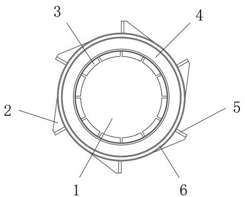
  • Multi-purpose hole head for screwdriver
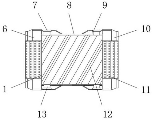
  • Multi-purpose hole head for screwdriver
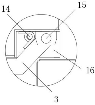
  • Multi-purpose hole head for screwdriver

Examples


Embodiment

[0023] Please refer to figure 2 As shown, the present invention provides a multi-purpose hole head for a screwdriver, including a hole former joint 6, a connecting column 8 and a connecting rod joint 10, and the hole former joint 6 and the connecting rod joint 10 are respectively fixed on both ends of the connecting column 8, forming a hole. The end faces of the tool joint 6 and the connecting column 8 are provided with mounting holes 1, the inner wall of the mounting hole 1 is provided with an internal thread 11, and both sides of the hole former joint 6 and the connecting rod joint 10 are provided with bolt holes 13. The outer wall of the port of the hole 13 is fixedly connected with a reinforcing rib 9, and the reinforcing rib 9 is provided with a receiving slot 7 at the outer port of the bolt hole 13. The hole former and the connecting rod are respectively connected with the multi-purpose hole head of the screwdriver. The connection operation is convenient, using bolts Th...


PUM


Abstract

The invention discloses a multi-purpose hole head of a screwdriver, comprising a hole former joint, a connecting column and a connecting rod joint. The end faces of the columns are all provided with mounting holes, the inner walls of the mounting holes are provided with internal threads, the two sides of the hole former joint and the connecting rod joint are provided with bolt holes, and the outer walls of the ports of the bolt holes are fixedly connected There is a reinforcing rib, and the reinforcing rib is provided with a receiving slot at the outer port of the bolt hole; the hole former and the connecting rod are respectively threaded with the multi-purpose hole head of the screwdriver, and the connection operation is convenient. The connector and the connecting rod and the connecting rod joint are firmly fixed, and the reinforcing ribs effectively enhance the structural strength of the bolt hole to prevent cracking during the fixing process. Wear and tear on the connecting part during the process.

Description

technical field [0001] The invention relates to the technical field of mining equipment accessories, in particular to a multi-purpose hole head of a screwdriver. Background technique [0002] At present, in coal mine exploration or operations, hole formers have been used in many ways, so the requirements for the connection between the connecting rod and the hole former are getting higher and higher. If the joint between the hole former and the connecting rod exerts less Torque, transferability can cause excessive torque, resulting in a lower coefficient of friction, and excessive torque can stretch, crack, or break the drill pipe, which is not desired, and can cause hole formers and connections The service life of the rod is shortened, and the maintenance cost is increased. At the same time, the connection between the connecting rod and the hole former will bulge during the operation of the hole former, and resistance will be generated during the drilling process, which will...

Claims


Application Information

Patent Timeline
Patent Type & Authority Patents(China)
IPC IPC(8): E21B17/04E21B17/042E21B10/32
CPCE21B17/04E21B17/0423E21B10/32
Inventor 段石郁江华宾海雄赵静郝学锋李亮
Owner ZOUCHENG YANKUANG TAIDE IND & TRADE CO LTD
Learn More