Damping electrical cabinet

A technology for electrical cabinets and shock absorbers, which is applied to springs/shock absorbers, anti-seismic equipment, vibration suppression adjustments, etc. It can solve problems such as difficulty in ensuring shock absorption effects, heavy weight, and fast aging of springs, and achieve improved shock absorption Effect, prolong service life, ensure the effect of shock absorption effect

Pending Publication Date: 2021-02-23
焦毅轩
10 Cites 0 Cited by

AI-Extracted Technical Summary

Problems solved by technology

However, since the weight of the electronic cabinet is often large, the spring installed at the bottom of the electrical cabinet completely bears the gravity of the electronic cabinet and interna...

Method used

Adopt above-mentioned scheme, described sucker 43 is adsorbed on the outer wall of described inner cabinet body 1, improves the matching degree of described side shock absorber 4 and described inner cabinet body 1, on the other hand, sucker 43 adsorption can be in Stretch to a certain extent to avoid rigid connection from reducing the shock absorption effect.
Adopt above-mentioned scheme, in described inner cabinet body 1, bearing is equipped with components and parts, described damping device 3 is arranged between described inner cabinet body 1 and outer cabinet body 2, reduces described inner cabinet body 1 suffered vibration, when the shock-absorbing electrical cabinet vibrates, the support part 31 and the shock-absorbing part 32 of the shock-absorbing part 32 bear the gravity of the inner cabinet body 1 at the same time, and when the shock occurs, the support part 31 first supports , the inner cabinet 1 is inclined along the arc-shaped top surface 311, when the inclination occ...

Abstract

The invention provides a damping electrical cabinet. The damping electrical cabinet comprises an inner cabinet body, an outer cabinet body and a damping device, wherein an accommodating space for accommodating components is formed in the inner cabinet body; the inner cabinet body is arranged in the outer cabinet body; the damping device is arranged between the inner cabinet body and the outer cabinet body; the damping device comprises a supporting part and damping parts; the supporting part is arranged at the gravity center of the cross section of the damping device; the supporting part is provided with an arc-shaped top surface; the top surface is connected with the bottom of the outer side of the inner cabinet body; the multiple damping parts are uniformly arranged around the supportingpart; when vibration occurs, the supporting part performs supporting firstly, and the inner cabinet body slides and inclines along the arc-shaped top surface; when inclination occurs, the damping parts reduce vibration, and the supporting part provides supporting for the inner cabinet body; and only the damping parts need to bear component force, so that the service life of springs in the dampingparts is prolonged, and the damping effect of the damping device is ensured.

Application Domain

Non-rotating vibration suppressionAnti-seismic devices

Technology Topic

PhysicsEngineering +1

Image

  • Damping electrical cabinet
  • Damping electrical cabinet
  • Damping electrical cabinet

Examples

  • Experimental program(1)

Example Embodiment

[0054]The exemplary embodiment will be described in detail herein, and examples thereof are shown in the drawings. The following description is related to the drawings, unless otherwise indicated, the same numbers in the drawings represent the same or similar elements. The embodiment described in the exemplary embodiments will not represent all embodiments consistent with the present invention. In contrast, examples of apparatus and methods consistent with some aspects of the invention, as detailed in the appended claims.
[0055]The terms used in the present invention are for the purpose of describing particular embodiments, not intended to limit the invention. "One", "one", "one", "" "and" "" as used in the present invention and the appended claims are also intended to include most forms unless the context clearly represents other meanings. It should also be understood that the terms "and / or" as used herein refer to any or from any or more of the associated listing items.
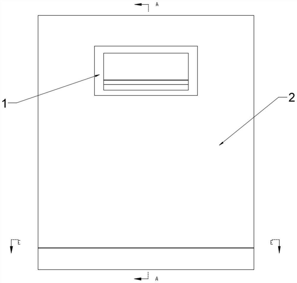
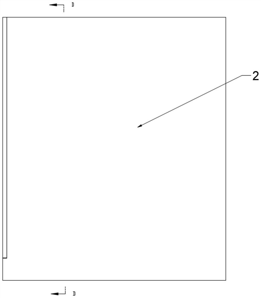
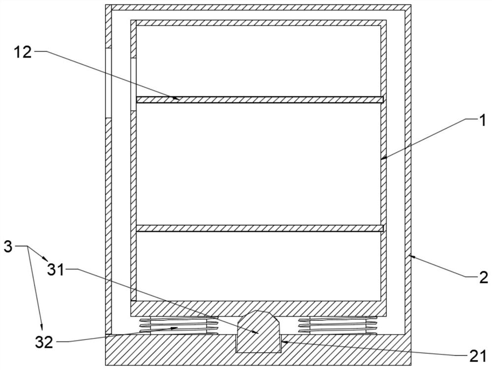
[0056]Such asfigure 1 ,25, 9, the present invention provides a damping electrical cabinet, including:
[0057]Inner cabinet 1, the inner cabinet 1 is provided with a housing space for conjunction with a component;
[0058]Outer closet 2, the inner cabinet 1 is disposed inside the outer cabinet 2;
[0059]The damping device 3, the damper device 3 is disposed between the inner cabinet 1 and the outer cabiner 2, and the damper device 3 includes a support member 31 and a shock absorbing member 32, the support member 31 is disposed. The center of gravity of the damper device 3, the support member 31 is provided with a circular arc-shaped top surface 311, and the top surface 311 is connected to the outer side bottom of the inner cabinet body 1, and the shock absorbing member 32 is provided with a plurality of, The damping member 32 is uniformly arranged around the support member 31.
[0060]With the above scheme, the inner cabinet body 1 carries a component, and the damper device 3 is disposed between the inner cabinet 1 and the outer cabiner 2, reducing the vibration of the inner cabinet 1, When the damping electrical cabinet occurs, the support member 31 and the damper member 32 of the shock absorbing member 32 simultaneously undertake the inner cabinet 1 gravity. When the vibration occurs, the support member 31 is first supported, said The inner cabinet body 1 is inclined along a circular top surface 311, and when the inclination occurs, the shock absorbing member 32 reduces the vibration, the support member 31 provides support for the inner cabinet body 1, only the shock absorbing member is required to bear the force. The life of the spring in the shock absorbing member 32 is extended to ensure the damping effect of the damper device 3.
[0061]In the specific implementation process, 4, 8 or 12 can be provided around the support member 31 around the support member 31.
[0062]During the specific implementation, the inner cabinet 1 and the same side of the outer cabinet body 2 are provided with an opening, and the inner cabinet 1 and the outer cabinet 2 are hinged at the opening with a door door for closing the interior space.
[0063]The above scheme is used to facilitate opening and closing the interior space of the inner cabinet 1 and the outer closer 2.
[0064]In a preferred embodiment of the invention, a viewing window is provided on the door, and the viewing window has a transparent material, the transparent material can be glass, plexiglass or polyethylene or the like.
[0065]The above scheme is used to observe the operating state of the electrical component by the viewing window.
[0066]Such asimage 3 ,4, 5, in the specific implementation process, the outer side of the inner cabinet 1 is provided with a circular arcuate support recess 111, and the support recess 111 is disposed at the center of the inner cabinet body 1, the support position, the support The groove 111 cooperates with the top surface 311.
[0067]In the specific implementation process, the grooves and top surface 311 of the support recess 111 each perform a parallelization process to improve the contact surface.
[0068]In a preferred embodiment of the invention, a lubricant is applied between the support recess 111 and the top surface 311, the lubricant can be lubricating oil, grease or graphite or the like.
[0069]With the above scheme, when a vibration occurs, the inner cabinet body 1 is inclined along a circular arc, the support recess 111 is fitted to the top surface 311, the support recess 111 and the top surface 311 along the contact surface. Slide, the two cooperate with improve the damping effect.
[0070]In the specific implementation process, the outer side of the inner cabinet 1 is provided with a support plate 11, and the support recess 111 is disposed on the support plate 11.
[0071]With the above scheme, when the vibration occurs, the support groove 111 is slid along the contact surface, and the sliding slide will be worn on the support recess 111, and the support recess 111 is disposed on the support plate 11 for easy replacement. Support plate 11.
[0072]In the specific implementation process, the connection method of the support plate 11 and the inner cabinet body 1 can be a bolt connection, a welding or a buckle connection.
[0073]In a preferred embodiment of the invention, the support plate 11 is a bolt connection with a connection method of the bottom of the inner cabinet 1.
[0074]In the specific implementation process, the support member 31 includes a lower support post 312 and an upper contact body 313, and the support post 312 is connected to the inner bottom portion of the outer closet 2, and the top surface 311 is on the contact body 313. surface.
[0075]In the specific implementation process, the contact body 313 can be a sphere or a partial sphere.
[0076]In a preferred embodiment of the invention, the support post 312 is integrally formed with the contact body 313.
[0077]In the specific implementation process, the outer closet 2 is provided with a receiving groove 21 extending outwardly from the inner side, and the support post 312 is connected to the bottom of the receiving groove 21.
[0078]With the above scheme, the support post 312 provides support for the contact body 313, increasing the physical strength of the support member 31, and extends the support member 31 life.
[0079]In a preferred embodiment of the invention, the top surface 311 is greater than the tall height of the housing groove 21.
[0080]Such asFigure 6 ,7As shown, in the specific implementation process, the shock absorbing member 32 includes a damper rod 321 and a first elastic member 322, and the first elastic member 322 is connected to the bottom end of the damper rod 321, the other end and the outer cabinet. The inner bottom of the body 2 is connected.
[0081]With the above scheme, when the vibration occurs, the inner cabinet body 1 is inclined, the damper member 32 is separated by the inclined inner cabinet body 1, and the damper rod 321 cooperates with the first elastic member 322 to achieve shock absorbing function.
[0082]In the specific implementation process, the outer tab body 2 is provided with a damper groove 22 extending from the inner direction, and the first elastic member 322 is connected to the bottom of the damper groove 22.
[0083]In a preferred embodiment of the invention, the damping member 32 further includes a second elastic member 323, wherein the second elastic member 323 surrounds the shock absorber rod 321, the second elastic member 323 is disposed in a shock absorbing. On the slot 22, one end is connected to the bottom of the outer closet body 2 and the other end is connected to the bottom of the inner cabinet body 1.
[0084]With the above scheme, the second elastic member 323 is shared by the first elastic member 322, and the two common functions are extended. On the one hand, the first elastic member 322 is used, and the other aspect increases the damping effect.
[0085]Such asFigure 6 ,8As shown, in the specific implementation process, the damping electrostatic cabinet also includes a side shock absorber 4, the side shock absorber 4 includes a contact plate 41 and a third elastic member 42, the contact plate 41 and the The outer cabinet 1 outer wall is fitted, and the third elastic member 42 is connected to the contact plate 41 and the other end is connected to the outer closet 2.
[0086]With the above scheme, when the inner cabinet 1 is inclined, the side shock absorber 4 shares the damping operation and improves the damping effect.
[0087]In the specific implementation process, the first elastic member 322, the second elastic member 323, and the third elastic member 42 can be a wave spring, a coil spring or a disc spring, and the like.
[0088]In a preferred embodiment of the invention, the suction cup 43 is provided on one side of the contact plate 41, the suction cup 43 adsorbed to the outer wall of the inner cabinet 1.
[0089]In the specific implementation process, the suction cup 43 is a vacuum chuck 43, which may be an elliptical suction cup 43, a corrugated suction cup 43 or a flat suction cup 43, and the like.
[0090]With the above scheme, the suction cup 43 adsorbed to the outer wall of the inner cabinet 1, improves the fitness of the side shock absorber 4 and the inner cabinet 1, on the other hand, and the suction cup 43 adsorption can be somewhat Stretching, avoiding rigid connections to reduce the damping effect.
[0091]Such asPicture 10As shown, in the specific implementation process, the inner cabinet 1 is provided with a sheet 12 for loading a component, and the inner cabinet 1 is provided with a slot 13, and the tablet 12 is connected to the slot 13. Cooperate.
[0092]With the above scheme, the tablet 12 is fitted to the slot 13, and the sheet 12 is fixed in the inner cabinet 1, and is connected to the slot 13 to facilitate disassembly.
[0093]In the specific implementation process, a magnetic block 14 is provided inside the side and the slot 13 in the slot 13, and when the strip 12 is fitted with the slot 13, the strip 12 side and the slot 13 The internal magnetic block 14 magnetic pole is mutually exclusive.
[0094]In a preferred embodiment of the invention, the magnetic block 14 is embedded inside the side of the buffold 12, the magnetic block 14, is exposed on the side; the magnetic block 14 is embedded inside the slot 13, The magnetic block 14 magnetic pole is exposed on the trough
[0095]With the above scheme, the magnet includes an N-pole and a S pole, and when the same magnetic pole of the two magnets is close to each other, it is repel each other, and there is a shake space between the tablets 12 and the slot 13, and the principle of magnetic pole mutual exclusion When the carton 12 sways, the magnet is shocked, and the rigid elastic member is not required to solve the problem of long-term use of the rigid elastic member for a long time.
[0096]It should be understood that in the present application, the above technical problems can be achieved in combination with each other, and various embodiments, feature can be combined with each other.
[0097]The above description of the disclosed embodiments will be made to those skilled in the art can be implemented or used. A variety of modifications to these embodiments will be apparent to those skilled in the art, and the general principles defined herein can be implemented in other embodiments without departing from the spirit or scope of the invention. Accordingly, the present invention will not be limited to the embodiments shown herein, but rather consistent with the widest range of principles and novel features disclosed herein.

PUM

no PUM

Description & Claims & Application Information

We can also present the details of the Description, Claims and Application information to help users get a comprehensive understanding of the technical details of the patent, such as background art, summary of invention, brief description of drawings, description of embodiments, and other original content. On the other hand, users can also determine the specific scope of protection of the technology through the list of claims; as well as understand the changes in the life cycle of the technology with the presentation of the patent timeline. Login to view more.

Similar technology patents

Punching positioning device

InactiveCN103394731AThe punching position is accurateExtended service life
Owner:STATE GRID CORP OF CHINA +1

Method for preparing abrasion-resistant super-hydrophobic ceramic coating through thermal spraying technology and product

ActiveCN105316619AExtended service lifegood self-cleaning
Owner:NINGBO INST OF MATERIALS TECH & ENG CHINESE ACADEMY OF SCI

Classification and recommendation of technical efficacy words

  • Extended service life
  • Guaranteed shock absorption

Fracturing manifold quick connecting device

Owner:YANTAI JEREH PETROLEUM EQUIP & TECH

Modified asphalt composition with creeping characteristic and preparation method thereof

InactiveCN102020859Aavoid rapid agingExtended service life
Owner:ZHEJIANG WOPUMAN HIGH NEW MATERIALS

Automobile shock absorber real-time adjusting and controlling system

ActiveCN105539049AGuaranteed shock absorption
Owner:WM MOTOR TECH GRP CO LTD

External heat dissipation device of computer chassis with high applicability

InactiveCN109032311Agood protectionGuaranteed shock absorption
Owner:SHANDONG BUSINESS INST
Why Eureka
Try Eureka