Diffractive optical element and manufacturing method thereof

A technology of diffractive optical element and manufacturing method, applied in the field of optics, can solve the problem of not being able to obtain better visual effects and the like

Inactive Publication Date: 2021-02-23
SHANGHAI NORTH OCEAN PHOTONICS CO LTD
View PDF0 Cites 2 Cited by
  • Summary
  • Abstract
  • Description
  • Claims
  • Application Information

AI Technical Summary

Problems solved by technology

Traditional DOE cannot be well applied to 3D visual structured light solutions
There are currently two main methods of use on the market, one is to use a single-point laser with side divergence, and directly split the beam through DOE to generate a speckle pattern of 5,000 to 60,000 points; the other is to use a VCSEL laser, and the laser itself consists of 100 to 500 points. Composition of the light source, the dot matrix of the light source is copied and spliced ​​by DOE to form a final speckle pattern of 5,000 to 60,000 points, but none of them can obtain better visual effects, so it is necessary to improve the traditional DOE

Method used


Image

  • Diffractive optical element and manufacturing method thereof
  • Diffractive optical element and manufacturing method thereof
  • Diffractive optical element and manufacturing method thereof

Examples


Embodiment Construction

[0043] The following description serves to disclose the present invention to enable those skilled in the art to carry out the present invention. The preferred embodiments described below are only examples, and those skilled in the art can devise other obvious variations. The basic principles of the present invention defined in the following description can be applied to other embodiments, variations, improvements, equivalents and other technical solutions without departing from the spirit and scope of the present invention.

[0044] Those skilled in the art should understand that in the disclosure of the present invention, the terms "vertical", "transverse", "upper", "lower", "front", "rear", "left", "right", " The orientation or positional relationship indicated by "vertical", "horizontal", "top", "bottom", "inner", "outer", etc. is based on the orientation or positional relationship shown in the drawings, which are only for the convenience of describing the present invention...


PUM


Abstract

The invention provides a manufacturing method of a diffractive optical element. The method comprises the following steps: determining parameters of the diffractive optical element; designing the diffractive optical element; manufacturing a diffractive optical element mother set; and assembling to form the diffractive optical element. The method can be applied to the field of 3D structured light, and is long in projection distance and high in precision.

Description

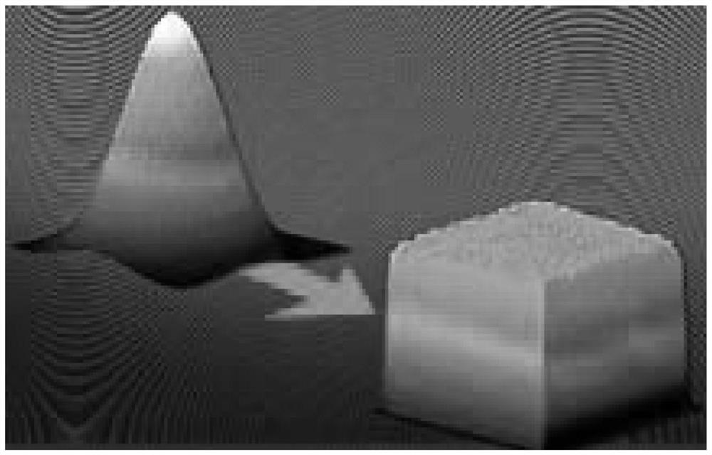
technical field [0001] The invention relates to the field of optics, and further relates to a diffractive optical element and a manufacturing method thereof. Background technique [0002] Diffractive Optical Elements (DOE for short) are usually used for laser shaping. Diffractive optical element is an optical element designed using the principle of diffractive optics. Usually, for incident laser light of a specific wavelength, the surface micro-nano structure is designed to adjust the energy and phase of the laser light to achieve the required output spot. [0003] Traditional diffractive optical elements mainly include beam shaping DOE, focus control DOE, beam splitting DOE and accessories of various diffractive elements. [0004] Reference manual attached figure 1 , the beam shaper is the most commonly used type of diffractive optical element, its function is to convert the Gaussian beam into a flat-top spot with uniform energy distribution, including flat-top beam shape...

Claims


Application Information

Patent Timeline
Patent Type & Authority Applications(China)
IPC IPC(8): G02B5/18
CPCG02B5/1847G02B5/1857
Inventor 黄河林涛楼歆晔丛森
Owner SHANGHAI NORTH OCEAN PHOTONICS CO LTD
Why Eureka
Try Eureka