Unit element beam splitting and combining interferometer
A single component, interferometer technology, applied in optical components, instruments, optics, etc., can solve the problems of difficult to read, can not take into account simplicity and readability, etc., and achieve the effect of high stability
- Summary
- Abstract
- Description
- Claims
- Application Information
AI Technical Summary
Problems solved by technology
Method used
Image
Examples
Embodiment 1
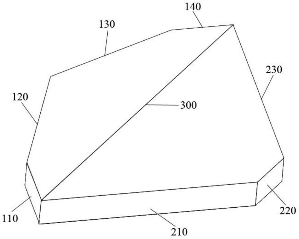
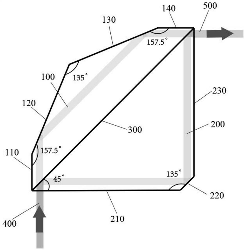
[0043] A single-element beam-splitting and combining interferometer, including elements, a light beam is divided into two beams after entering the element, that is, a first beam of light 100 and a second beam of light 200, and the first beam of light 100 and the second beam of light 200 After even and odd times of reflection in the component, the two beams of light are recombined in the component after reflection, and finally emitted from the combined beam of the component.
[0044] The element includes a beam-splitting plane 300, which is a polarization beam-splitting plane 300, that is, splitting light into orthogonal polarization components.
[0045] Alternatively, the light-splitting plane 300 is a non-polarized light-splitting plane, which is an ordinary light-splitting plane, that is, it is not sensitive to polarization.
[0046] The beam splitting plane 300 divides the light beam into two paths of light, that is, the first beam of light 100 and the second beam of light ...
Embodiment 2
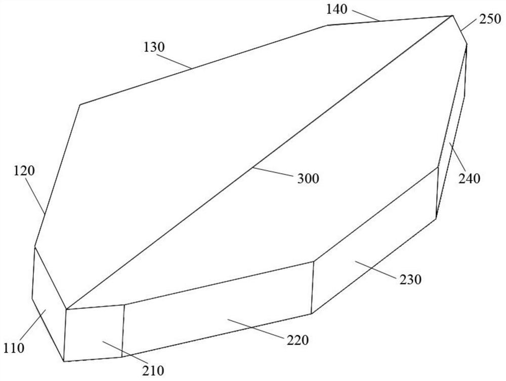
[0056] Based on the above-mentioned embodiment 1, the similarities will not be repeated, and the difference is that, as attached Figure 3-4 As shown, the first beam of light 100 undergoes 2 reflections in the element, and the second beam of light 200 undergoes 5 reflections in the element (including 2 reflections at the splitting plane 300 and 3 reflections at the side of the element), Ultimately the combined beam exits from the component.
[0057] The number of prism surfaces on the side of the element corresponding to the first beam of light 100 is four, namely mirror A1110, mirror A2120, mirror A3130, and mirror A4140, the angle between the mirror A1110 and the mirror A2120, the mirror A3130 and the mirror A4140 The included angles are all 154-160°, and the included angles between the mirror surface A2120 and the mirror surface A3130 are 132-138°.
[0058] Preferably, the included angle between the mirror A1110 and the mirror A2120, the included angle between the mirror A...
Embodiment 3
[0065] Based on the above-mentioned embodiment 2, construct a compact vector light field generating device, such as Figure 5 As shown, a 1 / 2 wave plate 600 is placed in front of the polarization interference prism. When the horizontally polarized vortex beam is incident on the 1 / 2 wave plate 600, the polarization direction is rotated to 2θ. According to Malius’ law, when the beam enters After the single-element beam-splitting and combining interferometer in Embodiment 2, if the beam-splitting plane 300 is polarized beam-splitting, the intensity ratio of the two beams divided inside is: cos 2 2θ sin 2 2θ. In addition, a 1 / 4 wave plate can be placed or not placed at the exit end of the component (polarization interference prism). If a 1 / 4 wave plate is placed and the optical axis direction is adjusted to 45°, the two beam components combine and exit After that, they are respectively modulated into left and right circularly polarized light. At this time, two left and right circ...
PUM
 Abstract
Description
Claims
Application Information
 - R&D
- Intellectual Property
- Life Sciences
- Materials
- Tech Scout
- Unparalleled Data Quality
- Higher Quality Content
- 60% Fewer Hallucinations
Browse by: Latest US Patents, China's latest patents, Technical Efficacy Thesaurus, Application Domain, Technology Topic, Popular Technical Reports.
© 2025 PatSnap. All rights reserved.Legal|Privacy policy|Modern Slavery Act Transparency Statement|Sitemap|About US| Contact US: help@patsnap.com


