Intelligent traffic system and control method thereof

An intelligent transportation system and traffic control technology, applied in the field of intelligent transportation, can solve the problems of heavy workload, inability to automatically adjust the lighting time of signal lights, low utilization rate of road traffic capacity, etc., and achieve the effect of improving utilization rate

Inactive Publication Date: 2021-02-23
王凯
View PDF4 Cites 5 Cited by
  • Summary
  • Abstract
  • Description
  • Claims
  • Application Information

AI Technical Summary

Problems solved by technology

[0002] The lighting time of each signal light (green light, red light and yellow light) in the traditional traffic signal indicating device is usually fixed, and can be manually adjusted if necessary. However, the traffic flow of each road is not constant. The traditional The traffic signal indicating device cannot automatically adjust the lighting time of

Method used


Image

  • Intelligent traffic system and control method thereof
  • Intelligent traffic system and control method thereof
  • Intelligent traffic system and control method thereof

Examples


Embodiment 1

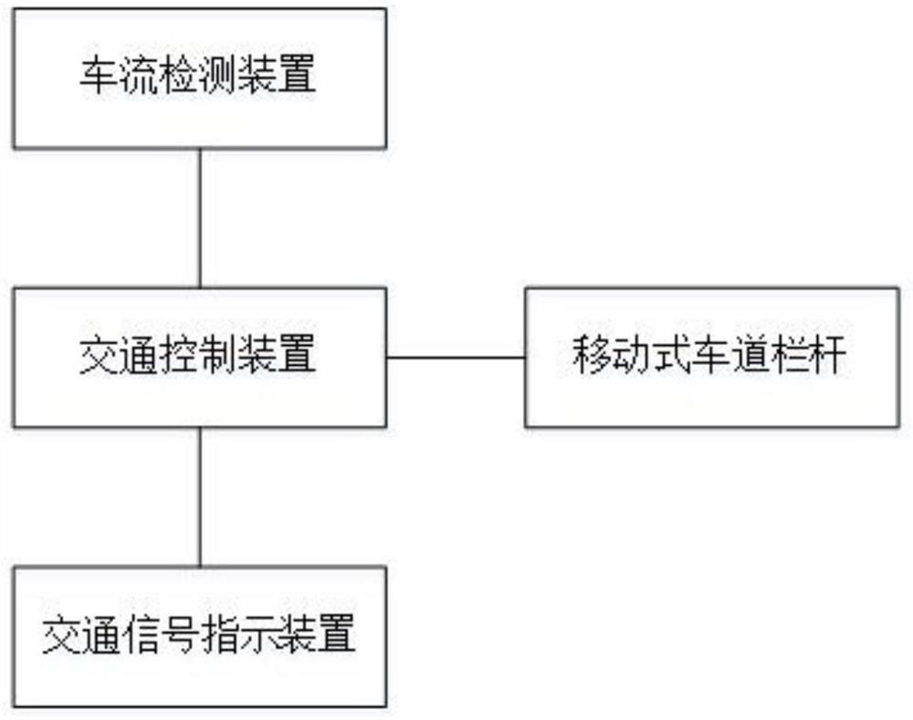
[0054] like figure 1 As shown, an intelligent transportation system includes a traffic control device, a vehicle flow detection device, a mobile lane railing and a traffic signal indicating device, and the traffic control device and the vehicle flow detecting device, the mobile lane railing and the traffic signal indicating device are connected through a wireless network Connect to communicate, such as 3G / 4G network.

[0055] The vehicle flow detection device is arranged at the entrance of each target road section, and is used to detect the traffic flow of the target road in each time period.

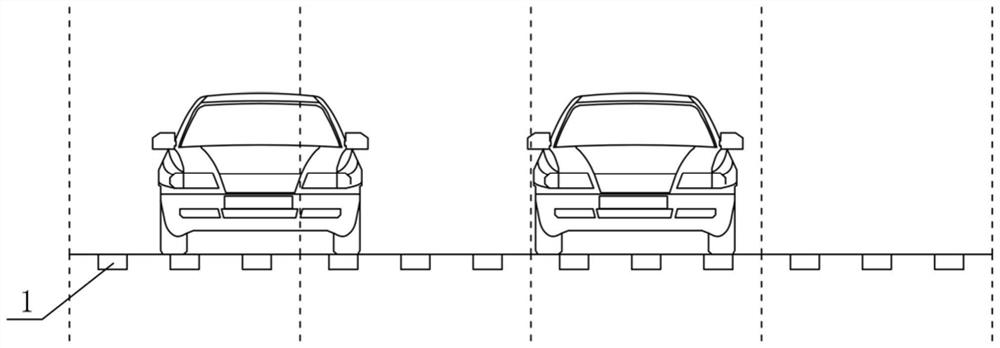
[0056] In some embodiments, the vehicle flow detection device includes an ultrasonic distance sensor 1 and a counting processor, such as figure 2 As shown, the ultrasonic distance sensor 1 is installed on the road at the entrance of the lane. The ultrasonic distance sensor 1 detects whether there is a vehicle passing by. The counting processor counts the vehicles according to the dete...

Embodiment 2

[0075] like Figure 7 As shown, a control method for an intelligent transportation system, comprising:

[0076] S1. The traffic flow detection device detects the traffic flow of the target road in each time period, and sends the detection results to the traffic control device.

[0077] The traffic detection device includes an ultrasonic distance sensor 1 and a counting processor. The ultrasonic distance sensor 1 is arranged on the road surface at the entrance of the lane. The ultrasonic distance sensor 1 detects whether a vehicle passes by. Count and send the counting result to the traffic control device.

[0078] If the two adjacent ultrasonic distance sensors 1 detect the vehicle within the preset time, the counting processor determines that it is the same vehicle, which solves the problem that the same vehicle is repeatedly counted due to the vehicle crossing the lane, etc., and improves the accuracy of vehicle counting.

[0079] S2. The traffic control device generates ...


PUM


Abstract

The invention discloses an intelligent traffic system and a control method thereof. The intelligent traffic system comprises a traffic flow detection device, a traffic control device and a traffic signal indicating device, wherein the traffic flow detection device is used for detecting the traffic flow of a target road in each time period; the traffic control device receives the detection result of the traffic flow detection device, generates a first instruction and a second instruction according to the detection result of the traffic flow detection device, is arranged on the road surface of the reversible lane, and is used for receiving the first instruction of the traffic control device and changing the reversible lane according to the first instruction; and the traffic signal indicatingdevice is arranged at the traffic intersection and is used for receiving the second instruction of the control device and adjusting the lightening time of each signal lamp according to the second instruction. The traffic flow is detected, and the lighting time of each signal lamp is adjusted according to the traffic flow, so that the utilization rate of the road traffic capacity can be enhanced.

Description

technical field [0001] The invention belongs to the technical field of intelligent transportation, and in particular relates to an intelligent transportation system and a control method thereof. Background technique [0002] The lighting time of each signal light (green light, red light and yellow light) in the traditional traffic signal indicating device is usually fixed, and can be manually adjusted if necessary. However, the traffic flow of each road is not constant. The traditional The traffic signal indicating device cannot automatically adjust the lighting time of each signal light according to the change of traffic flow, and the utilization rate of road traffic capacity is not high. In addition, in order to improve the problem of traffic congestion, some roads with many commuting vehicles are equipped with tidal lanes. However, in the prior art, the railings of the tidal lanes are manually moved, and the workload is heavy. Contents of the invention [0003] The pur...

Claims


Application Information

Patent Timeline
IPC IPC(8): G08G1/065G08G1/095G08G1/083G08G1/01
CPCG08G1/065G08G1/095G08G1/083G08G1/0104
Inventor 王凯
Owner 王凯
Why Eureka
Try Eureka