Pixel driving circuit and OLED display panel

A pixel driving circuit and driving transistor technology, applied in static indicators, instruments, etc., can solve the problems of increased leakage current of transistors, poor display effect of OLED display panels, etc., to improve charging and discharging capacity, stabilize display effect, and speed up switching. effect of speed

Inactive Publication Date: 2021-02-23
WUHAN CHINA STAR OPTOELECTRONICS SEMICON DISPLAY TECH CO LTD
View PDF7 Cites 12 Cited by
  • Summary
  • Abstract
  • Description
  • Claims
  • Application Information

AI Technical Summary

Problems solved by technology

[0003] However, in the traditional pixel driving circuit technical solution, the leakage current of the transistor will increase due to the photovoltaic effect under light conditions, which will lead to poor display effect of the OLED display panel at a lower refresh rate.

Method used


Image

  • Pixel driving circuit and OLED display panel
  • Pixel driving circuit and OLED display panel
  • Pixel driving circuit and OLED display panel

Examples


Embodiment Construction

[0033] The technical solutions in the embodiments of the present application will be clearly and completely described below in conjunction with the drawings in the embodiments of the present application. Apparently, the described embodiments are only some of the embodiments of the present application, rather than all the embodiments. Based on the embodiments in this application, all other embodiments obtained by those skilled in the art without making creative efforts belong to the scope of protection of this application.

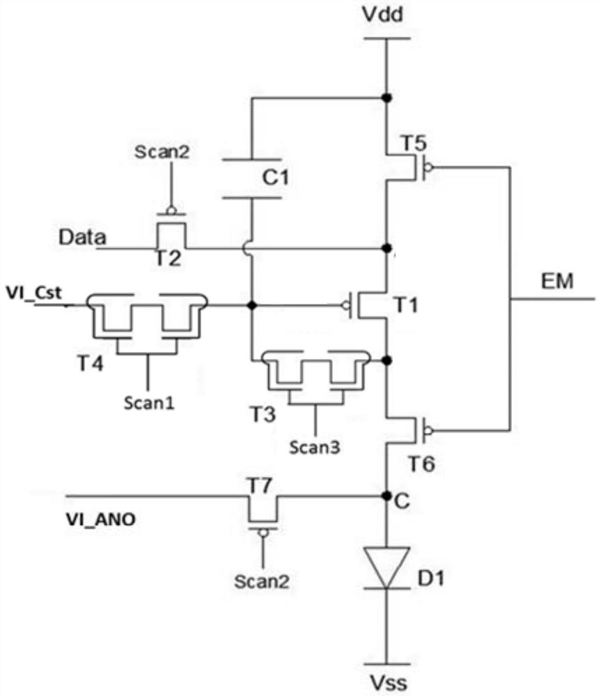
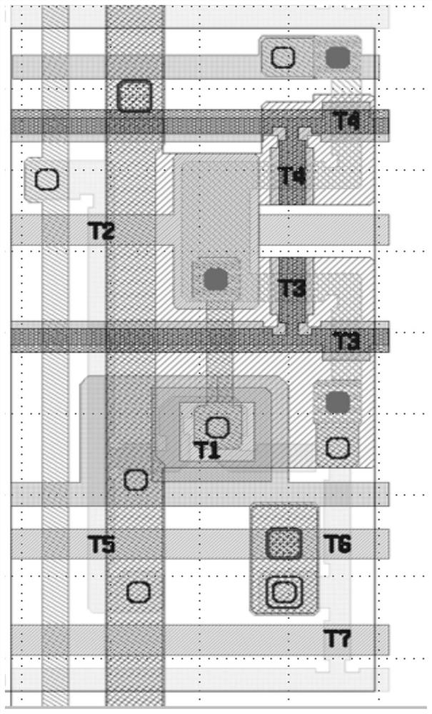
[0034] see figure 1 , figure 2 , figure 1 The first circuit schematic diagram of the pixel driving circuit provided by the embodiment of the present application; figure 2 It is a schematic wiring diagram of the pixel driving circuit provided by the embodiment of the present application. like figure 1 , figure 2 As shown, the embodiment of the present application provides a pixel driving circuit, which includes a light emitting device D1, a driving ...


PUM


Abstract

A pixel driving circuit provided by the invention comprises: a light emitting device which is connected in series with a light emitting loop formed by a first power supply signal and a second power supply signal; a driving transistor which is connected to the light emitting loop in series and used for controlling the current flowing through the light emitting loop; a first reset transistor, wherein the grid electrode of the first reset transistor is connected with a first scanning signal, wherein the source electrode is connected with a first reset signal, and the drain electrode is electrically connected with the grid electrode of the driving transistor; and a clamping transistor, wherein the grid electrode of the clamping transistor is connected with a second scanning signal, wherein thesource electrode of the clamping transistor is electrically connected with the drain electrode of the driving transistor, the drain electrode of the clamping transistor is electrically connected withthe grid electrode of the driving transistor, and the first reset transistor and/or the clamping transistor are/is a double-gate transistor. According to the OLED pixel driving circuit, the first reset transistor and/or the clamping transistor adopt/adopts the double-gate transistor, so that the increase of the leakage current of the transistor due to a photovoltaic effect can be avoided, the leakage current of the transistor can be effectively reduced, and the OLED display panel has a more stable display effect.

Description

technical field [0001] The present application relates to the field of display technology, in particular to a pixel driving circuit and an OLED display panel. Background technique [0002] The OLED (Organic Light Emitting Diode, Organic Light Emitting Diode) display panel has the advantages of high brightness, wide viewing angle, fast response speed, low power consumption, etc., and has been widely used in the field of high-performance display. With the development of multimedia, display panels are becoming more and more important. Correspondingly, the requirements for various types of display devices are getting higher and higher, especially in the field of smart phones, ultra-high-frequency drive displays, low-power drive displays, and low-frequency drive displays are all current and future development demand directions. [0003] However, in the traditional pixel driving circuit technical solution, the leakage current of the transistor will increase due to the photovoltai...

Claims


Application Information

Patent Timeline
Patent Type & Authority Applications(China)
IPC IPC(8): G09G3/3225
CPCG09G3/3225
Inventor 张淑媛陈建锋
Owner WUHAN CHINA STAR OPTOELECTRONICS SEMICON DISPLAY TECH CO LTD
Why Eureka
Try Eureka