Heat dissipation device for laser

A technology of heat dissipation device and laser, applied in laser cooling device, laser, laser parts and other directions, can solve the problems of internal structure damage, inability to dissipate heat, structure damage, etc., achieve efficient heat dissipation, meet long-term use load, and avoid high temperature heat accumulation effect

Active Publication Date: 2021-02-23
GUANGHUA LINGANG ENG APPL & TECH R&D (SHANGHAI) CO LTD
View PDF5 Cites 2 Cited by
  • Summary
  • Abstract
  • Description
  • Claims
  • Application Information

AI Technical Summary

Problems solved by technology

[0003] When the laser is used for a long time, it will generate high temperature, which is easy to cause damage to its structure. The existing structure usually provides a simple heat dissipation structure for simple heat dissipation fins. The heat is fully dissipated, and it is easy to cause heat accumulation to cause damage to the internal structure.

Method used


Image

  • Heat dissipation device for laser
  • Heat dissipation device for laser
  • Heat dissipation device for laser

Examples


Embodiment 1

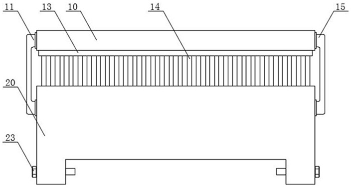
[0030] In summary, a water-cooling structure as described above, wherein, both sides of the cold row 10 are fixed with a fixed frame 12 by bolts, and the bottom of the fixed frame 12 is connected with the bottom frame 20 by bolts, providing a The fixed structure of the top cold row 10, the corners of the first fan 17 and the corners of the cold pipe 18 are provided with matching thread notches, and the cold pipe 18 and the first fan 17 are installed on the cold row 10 by bolts. On the frame body, both sides of the cold pipe 18 are provided with connecting pipes 19, and the connecting pipes 19 run through the outer walls of the cold row 10 on both sides, and the connecting pipes 19 on one side are connected with the water inlet pipe 11 provided, The connecting pipe 19 on the other side is connected with the return pipe 15 provided. Both sides of the water tank 37 are equipped with a water-through inner pipe 31. One side of the water tank 37 is fixed with a micro-water pump 38 by...

Embodiment 2

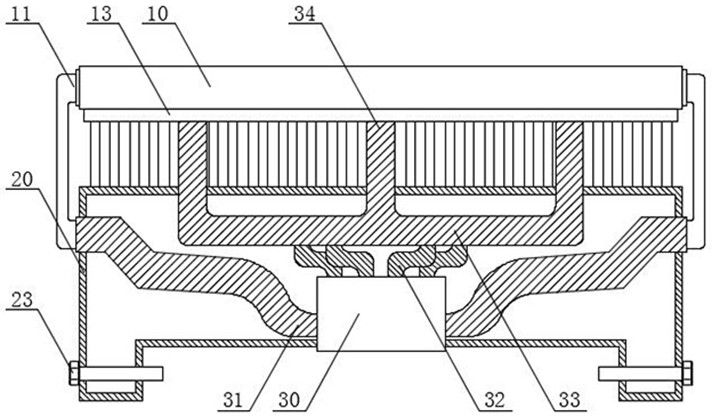
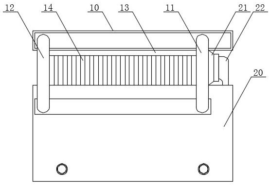
[0032] To sum up the above-mentioned air-cooled structure, the front side of the upper part of the chassis 20 is provided with a wind gathering cover 21, and the wind gathering cover 21 is used to collect the cold wind blown by the second fan 24, so as to ensure that the cold wind is always blown on the aluminum alloy. On the sheet 14, a ventilation pipe 22 is opened on one side of the wind gathering cover 21, and a second fan 24 is installed inside the bottom frame 20 by bolts, and a plurality of copper pipes 32 are welded on the upper end of the copper core 35. , the upper end of the copper tube 32 is provided with a copper plate 33, and the upper end of the copper plate 33 is welded with a through copper column 34, the copper tube 32, the copper plate 33 and the copper column 34 are all hollow structures, and the copper tube 32 runs through On the inner side of the copper plate 33, the copper tube 32 communicates with the copper column 34, and the upper part of the copper co...

Embodiment 3

[0034] In summary, a further optimized water-cooled and air-cooled structure is provided. The aluminum sheet 14 and the cold row 10 are separated by an asbestos board 13 to avoid the heat on the aluminum sheet 14 and the hot air blown out. The cold row 10 causes a direct impact, and avoids the temperature of the aluminum sheet 14 from being directly transmitted to the cold row 10. The structure of the water tank 37 is an O-shaped structure, and the copper core 35 is located at the center of the water tank 37. The copper core The outer side of 35 is attached to the inner wall of water tank 37, and the lower nozzle mouth of described copper tube 32 is inserted into the joint of copper core 35 and water tank 37, and when using, the water source of backflow has not only taken away the heat of copper core 35 surface, And take away part of the heat transferred to the copper pipe 32, accelerate the heat transfer speed, improve the effect of heat transfer effect, the top of the copper ...


PUM


Abstract

The invention discloses a heat dissipation device for a laser, and the device comprises: a cold row, which is provided with a frame groove on the upper surface, wherein the inner side of the frame groove is provided with a cold pipe, and is internally equipped with a plurality of first fans; a bottom frame, which is internally provided with a cavity and welded with a plurality of aluminum sheets at the upper end, wherein the plurality of aluminum sheets are combined into cooling fins, an asbestos plate is welded to the upper ends of the aluminum sheets, and a rectangular notch is formed in thelower portion of the bottom frame; through the arranged cold row, an arranged cold head and a matched auxiliary structure, two heat dissipation structures can be provided, efficient heat dissipationis provided in a water cooling mode, air cooling is assisted for heat dissipation, a bidirectional auxiliary cooling structure is formed through interaction of water cooling and air cooling, the heatdissipation effect is extremely excellent, the requirement for long-time service load can be met, an efficient heat dissipation effect can be provided, and the problem of high-temperature heat accumulation caused by long-time use is effectively avoided.

Description

technical field [0001] The invention relates to the field of auxiliary cooling devices, in particular to a cooling device for lasers. Background technique [0002] A laser is a device that emits laser light. According to the working medium, lasers can be divided into four categories: gas lasers, solid-state lasers, semiconductor lasers and dye lasers. Free electron lasers have also been developed, and high-power lasers are usually pulsed output. [0003] When the laser is used for a long time, it will generate high temperature, which is easy to cause damage to its structure. The existing structure usually provides a simple heat dissipation structure for simple heat dissipation fins. The heat is fully dissipated, and it is easy to cause heat accumulation to cause damage to the internal structure. Contents of the invention [0004] The object of the present invention is to provide a heat dissipation device for a laser, so as to solve the problems raised in the background a...

Claims


Application Information

Patent Timeline
Patent Type & Authority Applications(China)
IPC IPC(8): H01S5/024H01S3/04
CPCH01S5/02407H01S3/0407H01S3/0404
Inventor 张志平张文华王宁
Owner GUANGHUA LINGANG ENG APPL & TECH R&D (SHANGHAI) CO LTD
Why Eureka
Try Eureka