A charging and discharging control method, device and system

A technology of charging and discharging control and power supply relationship, which is applied in the computer field to achieve the effect of increasing battery life

Active Publication Date: 2022-03-25
HEFEI LCFC INFORMATION TECH
View PDF6 Cites 0 Cited by
  • Summary
  • Abstract
  • Description
  • Claims
  • Application Information

AI Technical Summary

Problems solved by technology

[0003] Although the above technology can realize mutual charging between two devices, there are some problems. In the current mutual charging scheme between devices, which device is the power supply party and which device is the power receiver is judged by the power of the device. For example, when device A has more power than device B, device A will be the power supply side and device B will be the power receiver

Method used


Image

  • A charging and discharging control method, device and system
  • A charging and discharging control method, device and system
  • A charging and discharging control method, device and system

Examples


Embodiment Construction

[0056] Various aspects and features of the present application are described herein with reference to the accompanying drawings.

[0057] It should be understood that various modifications may be made to the embodiments applied for herein. Accordingly, the above description should not be viewed as limiting, but only as exemplifications of embodiments. Those skilled in the art will envision other modifications within the scope and spirit of the application.

[0058] The accompanying drawings, which are incorporated in and constitute a part of this specification, illustrate embodiments of the application and, together with the general description of the application given above and the detailed description of the embodiments given below, serve to explain the embodiments of the application. principle.

[0059] These and other characteristics of the present application will become apparent from the following description of preferred forms of embodiment given as non-limiting examp...


PUM


Abstract

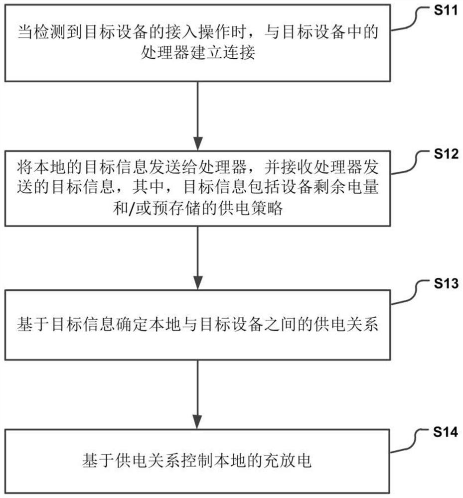
The present application discloses a charging and discharging control method, device and system, which are used to make the setting of charging and discharging between devices more flexible by users. The method includes: when an access operation of a target device is detected, establishing a connection with a processor in the target device; sending local target information to the processor, and receiving target information sent by the processor , wherein the target information includes the remaining power of the device and / or a pre-stored power supply strategy; determine the power supply relationship between the local and the target device based on the target information; and control local charging and discharging based on the power supply relationship. With the solution provided in this application, the user can adjust the power supply relationship between the local and target devices through the power supply strategy, so that the user can more flexibly set the charge and discharge between devices.

Description

technical field [0001] The present application relates to the field of computers, in particular to a charging and discharging control method, device and system. Background technique [0002] With the development of science and technology, mutual charging between two devices has been realized. This technology can be applied to mobile terminals, computers and other devices to realize end-to-end mutual charging. In the case of power banks, such technology can increase the battery life of devices with low power and improve user experience. [0003] Although the above technology can realize mutual charging between two devices, there are some problems. In the current mutual charging scheme between devices, which device is the power supplier and which device is the power receiver is judged by the power of the device. For example, when device A has more electricity than device B, device A is used as a power supply side, and device B is used as a power receiver. However, if the use...

Claims


Application Information

Patent Timeline
Patent Type & Authority Patents(China)
IPC IPC(8): H02J7/00G06Q50/06
CPCH02J7/00036H02J7/0047H02J7/00712G06Q50/06
Inventor 柏春李玉锋王建友
Owner HEFEI LCFC INFORMATION TECH
Why Eureka
Try Eureka