A fast-slow loop switching circuit for dcdc converter

A loop switching and converter technology, applied in the direction of converting DC power input to DC power output, instruments, electrical components, etc., can solve the problem that DCDC converters are difficult to take into account stability and response speed, and achieve the effect of improving response speed.

Active Publication Date: 2022-04-12
SG MICRO
View PDF9 Cites 0 Cited by
  • Summary
  • Abstract
  • Description
  • Claims
  • Application Information

AI Technical Summary

Problems solved by technology

Under different working conditions (input current limit or output constant voltage), it is difficult for DCDC converters to balance stability and response speed

Method used


Image

  • A fast-slow loop switching circuit for dcdc converter
  • A fast-slow loop switching circuit for dcdc converter
  • A fast-slow loop switching circuit for dcdc converter

Examples


Embodiment Construction

[0019] Below with the accompanying drawings ( Figure 1-Figure 3 ) to illustrate the present invention.

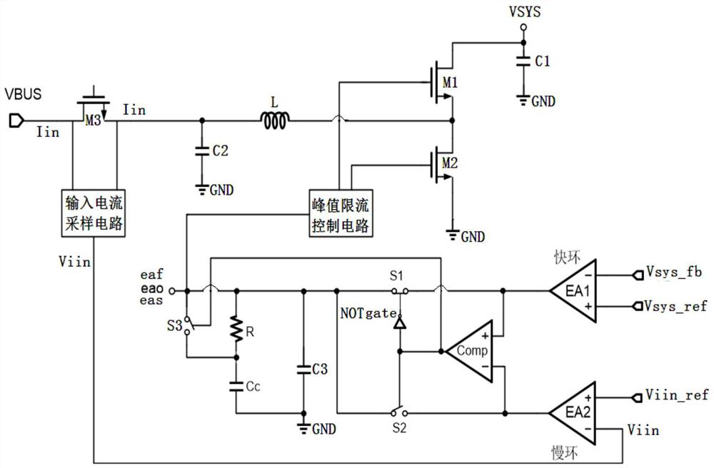
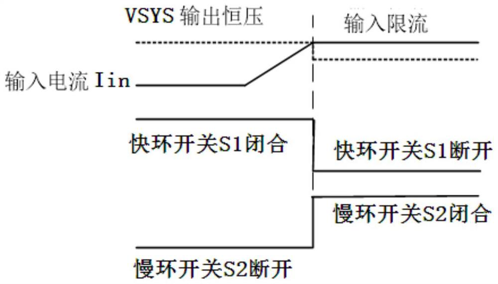
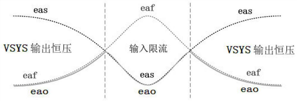
[0020] figure 1 It is a structural schematic diagram of a fast-slow loop switching circuit for a DC-DC converter implementing the present invention. figure 2 yes figure 1 Schematic diagram of the relationship between the medium input current Iin, the system output voltage VSYS, the fast loop switch S1, and the slow loop switch S2. image 3 yes figure 1 The relationship diagram of medium system output voltage VSYS, system input current limit and double-loop output voltage eao, fast-loop output voltage eaf, and slow-loop output voltage eas. Such as Figure 1 to Figure 3 As shown, a fast-slow loop switching circuit for a DCDC converter includes a first error amplifier EA1 and a second error amplifier EA2, the negative input terminal (-) of the first error amplifier EA1 is the system output voltage feedback signal Vsys_fb Access terminal, the positive input terminal (+)...


PUM


Abstract

A fast-slow loop switching circuit for a DCDC converter, through the combination and switching of the fast loop circuit meeting the response speed requirements and the slow loop circuit meeting the stability requirements, it can not only realize the fast dynamic response in the output constant voltage mode, It can also meet the stability requirements in the input current limiting protection mode, thereby helping to improve the comprehensive performance of the DCDC converter.

Description

technical field [0001] The present invention relates to the DCDC converter technology under the peak current limiting control mode, especially a fast-slow loop switching circuit for DCDC converter, through the combination of the fast loop circuit meeting the response speed requirement and the slow loop circuit meeting the stability requirement It can not only realize fast dynamic response in the output constant voltage mode, but also meet the stability requirement in the input current limiting protection mode, so as to improve the comprehensive performance of the DCDC converter. Background technique [0002] The DCDC converter using the peak current limit control mode includes two states, namely the usual output constant voltage state, and the input current limit state that needs to start the protection mechanism. The output constant voltage state involves the output constant voltage loop, and the input current limit state involved in the input current-limit loop. Under dif...

Claims


Application Information

Patent Timeline
Patent Type & Authority Patents(China)
IPC IPC(8): H02M3/158
CPCH02M3/158
Inventor 易新敏马玲莉
Owner SG MICRO
Why Eureka
Try Eureka