Measuring eye refraction
A technology of automatic measurement and measurement method, applied in the field of eye refraction measurement, which can solve problems such as lengthy, feasible problems, measurement errors, etc.
Pending Publication Date: 2021-02-23
斯格本斯眼科研究所有限公司
1 Cites 0 Cited by
AI-Extracted Technical Summary
Problems solved by technology
It is a lengthy and expensive process that requires a visit to a clinician as well as a multi-step test with specialized equipment to receive corrective lenses
[0005] A...
Method used
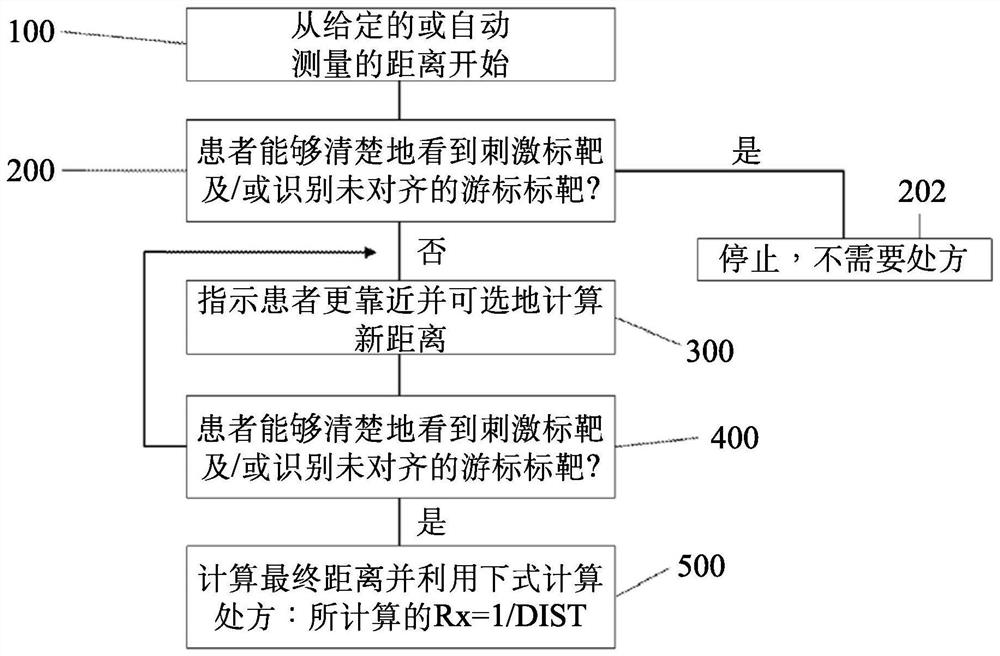
[0046] As shown in FIG. 3, an example method of eye refraction measurement includes, at step 100, a patient starting at a given distance from a mobile device running an application described herein. The mobile device is configured to display a visual stimulus that will indicate 20/20 or perfect vision, and the mobile device is configured so that the patient can see the screen from the starting distance. Next, at step 200, the patient is asked to indicate whether she can see the visual stimulus indicating 20/20 vision on the screen of the mobile device. If the patient is able to see the visual stimulus, the measurement will be terminated since no prescription is required at step 202 . If the patient cannot see the visual stimulus, then at step 300, the patient is asked to reduce the distance between herself and the visual stimulus on the mobile device, for example by walking towards the mobile device, and may calculate or measure The new distance between the patient and the mobile device. Next, at step 400, the patient indicates whether she is a...
Abstract
Methods, systems, and devices are provided for measuring eye refraction without a lens, and more particularly, for measuring eye refraction with a mobile device application. An exemplary method includes measuring a distance between a patient and a mobile device, presenting to the patient one or more visual targets sized and shaped to represent perfect vision such as by using Vernier targets or grating targets, instructing the patient to indicate whether the patient can accurately read the visual targets and, if not, to move closer to the mobile device until the patient can accurately read thevisual targets, calculating a vision prescription for the patient based on the visual targets and a final distance between the patient and the mobile device, and displaying the vision prescription forthe patient.
Application Domain
Image analysisAcquiring/recognising eyes +3
Technology Topic
Eye refractionVisual perception +3
Image
Examples
- Experimental program(1)
Example Embodiment
[0033]Hereinafter, the embodiments of the present disclosure will be described in detail with reference to the accompanying drawings. Those skilled in the art will realize that the described embodiments can be modified in various different ways, all of which do not depart from the spirit or scope of the present disclosure. Also, throughout the specification, similar reference numerals indicate similar elements.
[0034]The terminology used herein is only for the purpose of describing specific embodiments, and is not intended to limit the disclosure. Unless the context clearly indicates otherwise, the singular forms "a", "an" and "the" used herein are also intended to include the plural forms. In addition, it should be understood that when the terms "including" and/or "including" are used in this specification, they indicate the presence of the described features, wholes, steps, operations, elements and/or components, but do not exclude the presence or addition of one or more Other features, wholes, steps, operations, elements, components, and/or groups thereof. The term "and/or" as used herein includes any and all combinations of one or more related listed items. The term "coupled" refers to the physical relationship between two components, whereby these components are directly connected to each other or indirectly connected through one or more intermediate components.
[0035]It should be understood that the term "mobile device" or other similar terms used herein includes any portable computing device, such as a smart phone, a tablet computer, a notebook computer, a PDA, etc. The "mobile device" used herein is not necessarily limited to a device that is convenient to carry, but may also include a personal computer (PC) or other similar computing machines. The "mobile device" referred to herein is equipped with at least one or more processors (as generally known in the art), and an image acquisition unit that allows the user to capture a photo of a given subject (for example, camera). Moreover, the "mobile device" is preferably equipped with wired or wireless communication components to allow the device to communicate with external devices through a communication network. Similarly, the terms "mobile device application", "mobile application" or "application" as used herein refer to a computer program that can be executed by a processor installed in the "mobile device", such as existing The technology is generally known.
[0036]It should also be understood that the term "patient" or other similar terms as used herein includes any subject-human or animal, for which an eye assessment can be performed. The term "user" as used herein includes any entity capable of interacting with or controlling a mobile device. "User" can also be "patient", or "user" and "patient" can be separate entities, as described herein.
[0037]In addition, it should be understood that one or more of the following methods or aspects thereof may be executed by at least one processor. The processor can be implemented in a mobile device, as described herein. A memory configured to store program instructions may also be implemented in the mobile device, in which case the processor is specifically programmed to execute the stored program instructions, thereby performing one or more processes described further below. Moreover, it should be understood that the following method may be executed by a mobile device including the processor in combination with one or more additional components, as described in detail below.
[0038]Moreover, the method or aspect of the present disclosure can be implemented as a non-transitory computer-readable medium on a computer-readable medium containing executable program instructions executed by the processor. Examples of the computer-readable medium include, but are not limited to, ROM, RAM, compact disk (CD)-ROM, magnetic tape, floppy disk, flash drive, smart card, and optical data storage device. The computer-readable recording medium may also be distributed in a computer system coupled to a network, such as to store and execute the computer in a distributed manner through a telematics server (telematics server) or a controller area network (Controller Area Network; CAN) Readable media.
[0039]When determining the prescription of the patient, a process that does not require any optical lens is to change the viewing distance of the object used to measure the prescription by the patient, and this process can be used to obtain beneficial results similar to the prescription process using lenses. In optics and optometry, instead of changing the actual distance to the object, a negative lens can be used to form an image of the object at a distance close to the patient for the object that is actually far away from the patient. Because of this, moving the subject closer to the patient is often similar to having a negative lens capable of producing such an image. However, when trying to implement the prescription measurement process based on this distance change mechanism, the distance involved in the measurement (especially in refractive measurement) and the proximity (or close distance) to the patient provide objects that are far (or far away) from the patient usually Equivalent visual stimuli bring challenges. In some cases, you can try to manually measure the distance using a ruler or the like. However, manually measuring the distance may be inaccurate, time-consuming, and require specialized knowledge and expertise, which limits its usability. Simply moving the eye chart from farther away from the patient to a closer distance is not accurate, because as the eye chart moves, the angular letters on the eye chart become larger in size. Visual discrimination generally refers to the ability to recognize details in a visual image, and for the purpose of refractive measurement for this distance change process, consistent requirements for visual discrimination should be maintained for all distances. For example, if a larger angular size is used for a shorter distance, the refractive error will be underestimated because the requirement is lower than for objects at a longer distance. In other words, the visual acuity obtained in the refractive measurement should be the same for the far distance and the closer distance.
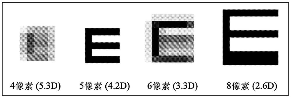
[0040]In one method, the prescription can be calculated as the reciprocal of the Maximum Distance of Best Visual Acuity (MDBA). However, when this principle is implemented in a system using a bitmap display (or raster display), the prior art still has problems. For example, US Patent No. 9,549,669 to Limon ("Limon") discusses measuring the refractive error of the eye based on the subject's distance metric. However, the method used in Limon has some fundamental flaws, resulting in limited feasibility. As some non-exhaustive examples, Limon uses optometry font letters as visual targets for refractive measurements. See, for example, U.S. Patent No. 9,549,669 to Limon,Figure 4 F,Figure 13 A. This method is a problem because it limits the number of prescriptions that can be accurately determined. For example, if a myopic patient needs to correct his vision to 20/16 vision, the 20/16 letter should be used to estimate the maximum distance for best vision (MDBA). Assuming that the patient needs 4.2D lenses to see the 20/16 letters, the MDBA will be 0.238m, and the linear size of the 20/16 letter E should be 0.387mm, or accurately, a standard 458PPI display (for example, for iPhone X) 5 pixels on the top. 5 pixels can be used to correctly display the letter E of the optometry font, because it consists of 3 horizontal strokes (black pixels) and 2 gaps (white pixels) in between, such asfigure 1 Shown in. Similarly, the prescription for 2.1D can correctly display the letter E, because at the MDBA of 0.476m, the linear letter size should be 10 pixels. However, by using the method in Limon, any required prescription that does not perfectly map to the requirements of these 5 pixel factors will require image scaling, resulting in distortion of the refraction font. For example, for anyone who needs a 3.3D prescription, the 20/16 letter E will be 6 pixels high. It is not possible to display strokes that are 1.2 pixels wide. Usually, the graphics rendering blurs the letters or one of the strokes is 2 pixels wide. Therefore, the Limon method cannot accurately measure prescriptions other than 4.2D and 2.1D. If the screen resolution is lower than 458PPI, the MDBA corresponding to a 5-pixel letter will be greater than 0.238m. This means that the highest prescription measurable by Limon's method will be lower than 4.2D. Therefore, using the method described in Limon will cause many prescriptions to be incorrectly measured.
[0041]Limon also discusses measuring the viewing distance to the camera, which most people cannot perform without specialized knowledge. Limon discusses using a reference target with a known size, and Limon discusses that in order to estimate the distance based on the reference target, the camera ratio should be given, which means providing EFL/Pitch. EFL is the effective focal length of the camera lens, and pitch is the physical distance between adjacent pixels on the image sensor. These numbers vary from camera to camera, and most people don't know it.
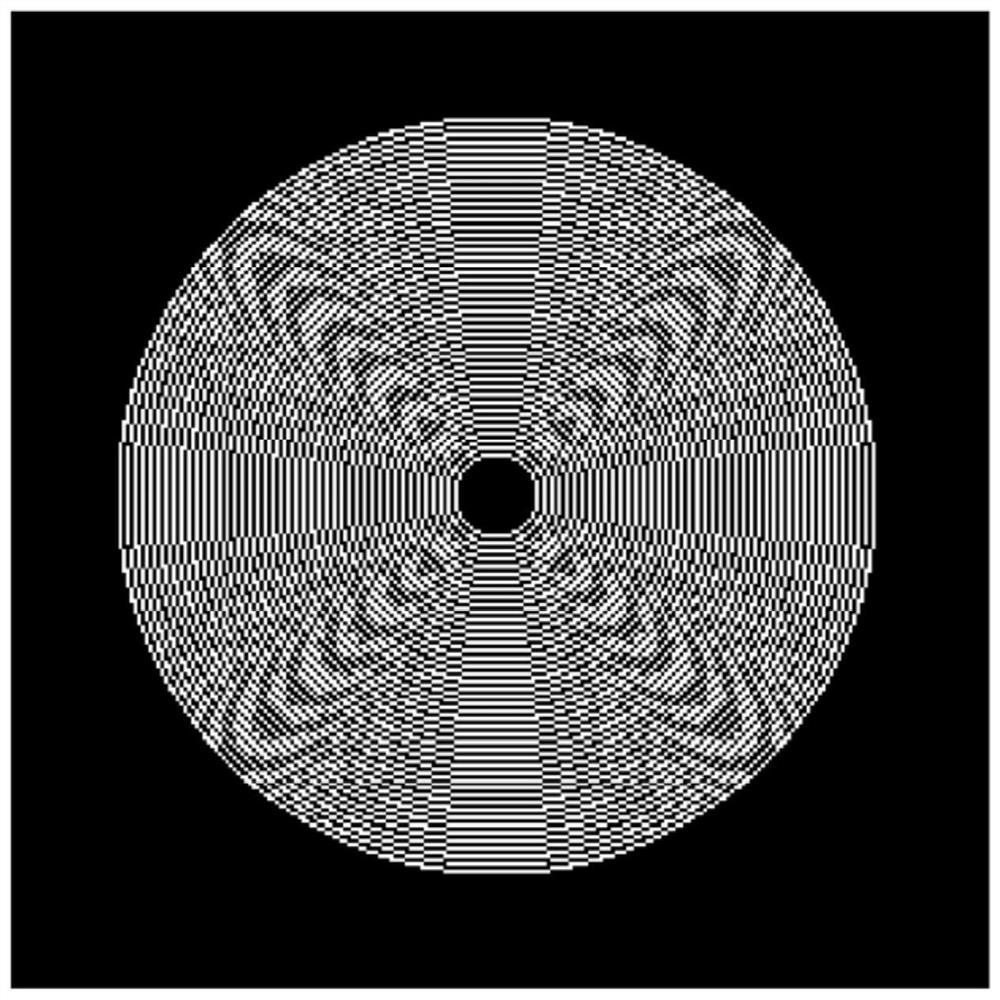
[0042]Limon also discusses the use of concentric ring patterns to measure astigmatism. Example image of LimonFigure 4 J uses low spatial frequencies. This means that when the patient sees these patterns, these patterns do not actually represent the patient's best corrected vision. Therefore, the distance at which the patient can clearly see these low spatial frequency patterns is not actually the correct MDBA of the patient. For example, again using a sample patient who wants to obtain 20/16 corrected vision, the spatial frequency he can see should be 37 cycles per degree. For example, for a patient who needs a 4.2D prescription, in order to see the concentric pattern, the distance from the eye to the screen will be 0.24m or less. At this distance, each ring of the concentric pattern will be 1 pixel wide on a 458PPI display, and even smaller on a lower resolution screen, which is impossible. When the ring width is only 1 pixel wide, some artifacts will appear on the image, such asfigure 2 Shown in. The root cause of these artifacts is that along the diagonal, the spatial frequency is 1.414 times the horizontal or vertical frequency, so it cannot be displayed correctly because it is not an integer. The screen resolution (that is, the screen spatial frequency) is only twice the ring in the horizontal or vertical direction. According to Nyquist's theorem, the screen resolution is only large enough to make concentric patterns displayed correctly in the horizontal and vertical directions, but not enough to display correctly in the diagonal direction. This leads to aliasing, which results in artifact patterns. In other words, for anyone who wants to get correct results through an eye test, the screen resolution of an ordinary mobile device is not high enough to use the method taught in Limon. The human eye cannot see a single pixel. If they can, people will see pixelated images on their screens. Since low spatial frequency patterns must be used, the correct diopter that Limon's method can measure is limited to low-end and not very accurate vision correction.
[0043]For these and other reasons, the method in Limon is not effective for many people who need a simple way to measure eye refractive without the expense and trouble of visiting a clinician. Therefore, although attempts have been made to simplify the prescription determination process, there are serious shortcomings in the current methods, resulting in limited use, measurement errors, and feasibility issues. Therefore, methods, devices, and systems are needed to measure eye refractive index without using lenses, especially for mobile device applications for eye refractive measurement.
[0044]Now referring to the embodiments of the present disclosure, measuring eye refractive is something that affects the majority of the adult American population and more international populations. Many people receive some form of eye refractive measurement in their adult life. Even people who have not suffered any type of impaired vision often undergo eye examinations throughout their lives to confirm that they do not need vision correction. People who do have some kind of impaired vision often need to undergo eye examinations every year, because many corrective lens prescription Can only accept up to 1 year. Therefore, most adults and many children accept or should receive regular eye examinations, which require expensive equipment, long-term examinations, and expensive expenses.
[0045]To this end, this article discloses technologies related to mobile device applications for measuring eye refractive index. Without the use of external accessories or appendages, the mobile application can measure the refractive index of the eye based on the basic interaction between the patient and the equipment on the mobile device (such as a display and a camera). Instead of using refractive lenses, the method disclosed herein determines the prescription by measuring the distance at which the patient can clearly see the irritant. Change the distance between the patient and the irritant, so corrective lenses are not required. This method can be used by anyone who needs eye refractive measurement, especially for people with myopia, as described in detail below.
[0046]Such asimage 3 An example method of eye refractive measurement shown in includes: in step 100, the patient starts at a given distance from the mobile device on which the application described herein is running. The mobile device is configured to display a visual stimulus that will indicate 20/20 or perfect vision, and the mobile device is configured so that the patient can see the screen from the starting distance. Next, in step 200, the patient is asked to indicate whether she can see the visual stimulus marked 20/20 vision on the screen of the mobile device. If the patient can see the visual stimulus, the measurement will be terminated because no prescription is required in step 202. If the patient cannot see the visual stimulus, in step 300, the patient is required to reduce the distance between herself and the visual stimulus on the mobile device, for example, by walking toward the mobile device, and can calculate or measure The new distance between the patient and the mobile device. Next, in step 400, the patient indicates whether she can see the visual stimulus. Repeat the process of observing the visual stimulus shown and reducing the distance as necessary to clearly see the stimulus until the patient can clearly see the visual stimulus on the mobile device. In step 500, at this distance, the patient's prescription is calculated by calculating 1 divided by the distance in meters (here, the visual stimulus is clear). By using high-resolution cameras installed in many modern mobile devices to calculate alignment and distance (discussed in detail below) combined with the custom-designed image processing algorithms described in this article, high-precision eye refractive measurements can be obtained. The entire processing is executed locally on the mobile device itself; therefore, the application does not need to send any data to the remote server for processing. Based on the measurements made, a high-precision prescription can be calculated for the patient (especially for myopic patients for whom many other measurement methods currently on the market are not available).
[0047]Generally speaking, the prescription is provided by listing the values of the spherical and cylindrical surfaces of each eye. The spherical value indicates the size of the lens power measured in diopter (D) for correcting myopia or hyperopia. If the number that appears under this heading has a negative sign, the patient is nearsighted, and if the number has a positive sign, the patient is hyperopic. The term "spherical" indicates that the correction of myopia or hyperopia is spherical, meaning that it is equal in all meridians of the eye. The cylinder indicates the size of the lens power required to correct any astigmatism of the patient. The number of the cylinder can have a negative sign (for the correction of myopic astigmatism) or a positive sign (for the hyperopic astigmatism) in front of the number. The term "cylindrical" indicates that the lens power added to correct astigmatism is not spherical, but is shaped so that a meridian has no additional curvature, and the meridian perpendicular to the "unadded power" meridian contains the maximum for correcting astigmatism Degree and curvature of lens. When detecting astigmatism, an axis is also provided. This figure shows that the cylindrical power lens meridian used to correct astigmatism is not included. The axis is defined by numbers from 1 to 180, where the number 90 corresponds to the vertical meridian of the eye, and the number 180 corresponds to the horizontal meridian. The meridian in the eye is a circle with constant longitude passing through the iris of the eye. For example, if the circle eye is a clock face, the line connecting 12 o'clock and 6 o'clock will be a meridian, the line connecting 3 o'clock and 9 o'clock will be another meridian, and so on.
[0048]Figure 4 An exemplary schematic view of a mobile device architecture according to an embodiment of the disclosure is shown. Such asFigure 4 As shown in, the mobile device 102 may include multiple components, including but not limited to a processor (for example, a central processing unit (CPU)) 110, a memory 120, a wireless communication unit 130, an input unit 140, and an output unit 150. It should be noted thatFigure 4 The architecture described in is simplified and used for example purposes only. It should be noted thatFigure 4 The architecture shown in is simplified and for demonstration purposes only. In view of the wide variety of mobile devices sold in the market, the architecture of the mobile device 102 mentioned in this disclosure can be modified in any suitable manner understood by those skilled in the art according to the current claims.Figure 4 The mobile device architecture shown in should be regarded as an example only, and should not be regarded as limiting the scope of the present disclosure.
[0049]The components of the mobile device 102 will be briefly described below, and the processor 110 can control the operation of the mobile device 102. More specifically, the processor 110 is operable to control and interact with multiple components installed in the mobile device 102, such asFigure 4 Shown in. For example, the memory 120 may store program instructions executable by the processor 110. The mobile applications described herein may be stored in the memory 120 in the form of program instructions to be executed by the processor 110. The wireless communication unit 130 may allow the mobile device 102 to transmit data to and receive data from one or more external devices through a communication network. The input unit 140 enables the mobile device 102 to receive various types of input, such as audio/video input, user input, data input, and so on. To this end, the input unit 140 may be composed of multiple input devices for receiving various types of input, including, for example, a camera 142 (that is, an "image acquisition unit"), a touch screen 144, a microphone, one or more buttons or switches, Gyroscope 146, etc. The input device included in the input 140 can be manipulated by the user. For example, the user may use the camera 142 to capture a photo by pressing the touch screen 144 in a recognition manner (that is, a manner recognized by the processor 110). The camera 142 may include a front-facing camera. The camera 142 may also include a rear-facing camera, but the forward-facing camera is mainly used in this document. It should be noted that the term "image acquisition unit" used herein may refer to the camera 142, but is not limited thereto. For example, the "image acquisition unit" may refer to a program that acquires an image of a patient stored locally in the memory 120 or remotely stored on a server. The output unit 150 may display information on the display screen 152 for the user to view. The display screen 152 may also be configured to accept one or more inputs through various mechanisms known in the art, such as a user tapping or pressing the screen 152. The output unit 150 may further include a flash generating device 154 (ie, a "flash"), which is a light source capable of generating a light beam. The flash generating device 154 may be configured to generate a flash of light during the acquisition of an image by the camera 142.
[0050]Therefore, the mobile device 102 can be programmed to allow it to perform the techniques for eye refractive measurement described below.
[0051]In use, the patient should place the mobile device 102 in a position where the patient can see the display screen 152 and can be seen by the image acquisition unit such as the camera 142. For example, the patient can place the mobile device 102 on a table, a shelf, fix it to a wall, or the like. The application on the mobile device 102 requires that the starting distance between the patient and the mobile device 102 be known by the mobile device 102. To achieve this, the patient can start at a known distance away from the mobile device 102, and the distance between the patient and the mobile device 102 can be provided to the mobile device 102, or the application can automatically measure the mobile device 120 and the patient in various ways. the distance between. In all these measurement methods and generally in the entire interaction between the patient and the application on the mobile device 102, the application can provide real-time guidance to the user in the form of instructions and/or graphics 210 displayed on the display screen 152, in general Help users to make correct measurements and use. Then, the information received by the mobile device 102 from the patient through various inputs and the information received by the camera 142 can be processed by the processor 110 to determine the distance between the patient and the mobile device.
[0052]The starting distance between the patient and the mobile device 102 may be a set distance, for example, between about 2 to 40 feet, such as 8 feet, 10 feet, 12 feet, 14 feet, 16 feet, 18 feet, 20 feet, 22 feet , 24 feet, 26 feet, etc. In order to clearly see the visual stimulus representing 20/20 vision, myopic patients often need to be at a distance shorter than 6.1 meters (20 feet), such as 0.5 meters (1.64 feet). The spherical equivalent correction will be the inverse of the distance, in this case 1/0.5=2D. Therefore, about 20 feet is usually used as the starting distance for patients using the app.
[0053]The starting distance between the patient and the mobile device 102 can also be manually provided to the mobile device 102 by the patient or a second party, and the input unit 140 is used to provide the distance through various mechanisms, such as using voice commands, physical typing through the touch screen 144, remote control, and the like. The patient must be able to measure the distance using this method, for example, by using a tape measure.
[0054]The starting distance can also be automatically measured by the application by using the mobile device 102, the input unit 140 and/or the camera 142 and one or more suitable image processing algorithms known in the art. This is for the patient to measure The simpler preferred method. For example, in the following discussion, various suitable image processing algorithms may be used, such as an adaptive thresholding algorithm. There are various methods to measure the distance between the patient and the mobile device 102. For example, such asFigure 5 As shown in, the application can measure the distance between the eyes of the patient (IPD) in the image and then calculate the distance using the following formula:
[0055]VD=PDP/tanθ
[0056]Among them, VD is the viewing distance between the patient and the camera 142, PDP is the physical size (IPD) of the distance within the pupil, and θ is the span angle of the half IPD.
[0057]For a single patient, PDP can be measured in advance by using a ruler or can be measured by processing a snapshot of the patient's face, and calculated using the following formula:
[0058]PDP=(PDX/IRSX)×12
[0059]Among them, PDX is the IPD in pixels, and IRSX is the patient's iris diameter in pixels. The value of θ in the above formula is in degrees. It is converted from pixels to angles by the pixel to angle conversion factor P2A. The conversion factor can be determined by the measurement using the gyroscope 146 of the mobile device 102 and the tracking image offset when the device is rotated.Figure 6 and7For explanations and examples.
[0060]Such asFigure 6 and7As shown in, in order to determine theta and the conversion factor P2A from pixel to angle, the patient can first point the camera 142 at the object in the room, preferably a few meters away, for example, between about 2 meters and about 20 meters, for example About 2 meters, 3 meters, 4 meters, 5 meters, etc. Next, in step 600, the mobile device 102 starts sampling the gyroscope data 146, and in step 602, starts sampling multiple video frames from the camera 142. Next, in step 604, the patient can slightly rotate the mobile device 102, so that the image captured by the camera 142 will be shifted byFigure 6 The offset point shown in the mark. Next, in step 606, the sampling of both the gyroscope data 146 and the video frame of the camera 142 is stopped. In step 608, the rotation angle θ can be measured by the data from the gyroscope 146 using the data from the mobile device 102 when it is shifted or rotated. The image offset (in pixels) can be determined by object tracking or optical flow tracking. For example, in step 610, one or more algorithms known in the prior art are used to track multiple images taken by the camera 142. The feature points on the image and the tracked feature points are summarized to determine the feature point offset S. Next, in step 612, the pixel-angle conversion factor is determined by dividing the feature point offset S by the rotation angle θ.
[0061]In this application, the operations in this article will be automated, only requiring the user to follow several simple steps: first align the camera 142, may enter the manual measurement PDP in some methods of the application, and turn the camera 142 Align objects from a few meters away, then shift the camera 142. This application automatically processes the image captured by the mobile device 102. Further, the PDP and angular proportional factors are determined and saved in the mobile device 102 as two constants for the patient and the mobile device 102. This process is only calibrated at first time, and there is no need to recalibrate (because the distance between the patient and the mobile device 102 is continuously used during the application).
[0062]Another method of determining the viewing distance can also be used, which similar but not, the measurement PDP can be used. This method is especially useful when viewing the distance. Such asFigure 8A-9As shown in step 700, the patient covers an eye and views the stimulus on the display screen 152 of the mobile device 102, and the camera 142 captures the image of the viewed eye, and the processor 110 processes the image. The method can include: At step 702, it is detected whether there is an unscated eye in the image, and at step 704, it is determined how many unscated eyes are present. If there are two eyes in step 704, then at step 706, the patient covers one eye by the speaker in the display screen 152 and / or device 102; if there is no eye in step 704, the method indicates at step 708. The patient blinked and at step 710, using the camera 142 to continue to capture multiple images to determine if the patient is blinking. The image is successfully captured to the help device 102, at step 712, the application can process the image to detect the blinking and store the position in the image, so that when another image can be, the application can determine the position of the eye to be in the image. Once the method detects that only one eye is visible, then in step 714, the software sub-application running in the overall application on the device 102 is handled by the circle to the iris boundary and measuring the iris diameter of the pixel unit. The image of the eye is to extract an iris edge. Next, at step 716, the viewing distance is calculated based on the diameter calculated from these images by the following formula:
[0063]VD = 6 / [TAN (IID / P2A)]
[0064]Among them, the IID is the diameter of the iris of the patient in pixels, and the P2A is a pixel-angle conversion factor, which is based on the top andFigure 6 and7The description is determined. Therefore, the patient can be used to comply with the above steps by another person using the mobile device 102 to allow the application to obtain the necessary information.
[0065]Another method for measuring the viewing distance is a change in the size of the face of the patient captured by the mobile device 102, such asFigure 10 and11Indicated in it. Before using this application, patients need to create a 3D contour of his own face. Patients must align the camera 142 to his face and rotate the camera 142 around its face, and take a plurality of facial photos from different angles. You can perform a single-grade SLAM (simultaneous positioning and mapping; Simultaneous localization and mapping) analysis to create a 3D outline of the patient's face. SLAM is a computer visual approach usually used in robotics, such as J.civera et al. "Inverse Depth Parametrization for Monocular Slam," IEETRANSATIONS ON ROBOTICS, VOL.24, No.5, PP.932-945, OCT . 2008, it can be at http://ieeexplore.ieee.org/stamp/stamp.jsp? TP = & amumber = 4637878 & isnum ber = 466322 Found and its overall is included herein. In this paper, a real-time (30 Hz) fully automatic 3-D SLAM system is provided, and its characteristic is a hand-held single camera method without additional sensing. However, alternative 3D mapping methods can be used herein. For example, an alternative method of capturing the 3D contour is to identify the camera through a face recognition camera, such as those available in the iPhone X.
[0066]Therefore, the patient initially captures his face's 3D outline. The application has the initial contour of the user's face, and compares the image with the initial contour during use. During use of this application, at step 800, the application retrieves the 3D contour of the surface of the patient, and at step 802, according to the given viewing or reference distance Rd (e.g., 1 m distance) and P2A (as described above) Recreate a facial image. Next, at step 804, the camera 142 captures the image of the face of the patient in real time during use, and at step 806, the application detects several facial features on the face of the patient. Next, at step 808, the application calculates the overall distance between the pixels, and at step 810, the characteristic interlayer distance ratio is compared between the reference 3D profile provided by the patient, thereby obtaining the location The ratio of the characteristic interval IFC and reference feature value IFR. Next, at step 812, the distance is calculated by multiplying a given viewing or reference distance RD with the ratio of the reference feature value IFC and the reference feature value IFR:
[0067]Distance = rd × (IFC / IFR)
[0068]Therefore, in order to measure the viewing distance, the surface size of the given distance is first calculated from the face size that is recreated according to the 3D face profile, and then the ratio is multiplied by a given view distance of the recreated face. It is also necessary to match the face image captured by the recreated reference face direction with the distance determination. Further, in order to minimize the error, the ratio calculated above can be a plurality of facial features (eg, from the distance from the eyes to the nose, from the distance to the distance, the distance between the eyes, and the distance between the eyes) average value.
[0069]One of the above methods, the application can determine the viewing distance between the patient and the mobile device 102.
[0070]After determining the viewing distance, the mobile device 102 is configured to display a visual stimulus, which will indicate 20/20 or perfect vision of the viewing distance. For example, the output unit 150 can display information to the patient on the display screen 152, and processor 110 can determine the displayed content. Therefore, the size of the displayed visual stimuli can vary depending on the distance between the patient and the mobile device 102. For example, if the viewing distance is 2 meters, and accordingly, the visual stimuli is displayed in a standard 20/20 size, the application determines that the patient can be moved from 2 meters to 1 meter, the size of the visual stimuli can be Reduce half of the previous standard 20/20 size, so that the angle size of the visual stimuli will remain 20/20. Thus, the viewing distance between the measured patient and the mobile device 102 can affect the size of the visual stimulus, so that the application will change the displayed linear size in accordance with the distance.
[0071]Although visual stimuli can take a variety of forms, one of the preferred methods is to use a vernier stimuli. This is especially true when the patient has a near view, since the patients with myopia must be close to the mobile device 102, and when the viewing distance is short, the optometry font (such as Snello letters) may not display correctly, as described above about Limon. Therefore, a cursor stimulus (high or low contrast) is preferably used.
[0072]Figure 12 and13Two examples of the cursor stimuli are displayed. Patient comparisonFigure 12 orFigure 13 The stimulus shown and marked from which one of the four tutoring targets is not aligned. The color of the target can have high contrast, such asFigure 12 During the present, or have a low contrast, such asFigure 13 Indicated in it. For patients, low contrast targets are more difficult, so the resulting refractive measurements will be more accurate.
[0073]During the test, the patient identifies an unsigned target. If the patient does not correctly identifies the unsatisfactory visual stimuli, the patient is required to reduce the distance between her own and mobile device 102, for example by moving to the mobile device 102. For example, the output unit 150 can display disorderly stimulating on display screen 152, and the application can determine if the patient's response is correct. If the patient does not correctly identify the unsigned stimulus, the application can communicate with the patient by the speaker or the like by the display screen 152, by means of the patient, or the like to be closer to the display device 102. At closer distance, the patient then reports which one is an unsatisfactory visual stimulus. If she still does not recognize properly, she is again closer to the visual stimuli until the patient can clearly see the visual stimulator on the mobile device 102 and correctly identify the unsigned target. Each new distance can be automatically determined by the mobile device 102, or can be manually input by the mobile device 102 or can be manually input by the patient or the second party. Moreover, in each of the steps, processor 110 can receive input and coordinate and process the output from the user.
[0074]Another preferred test method is to use a grating test.Figure 14 Examples of the target used in the grating test, such as one or more blocks.Figure 14 An example embodiment with four boxes is displayed. One of the boxes has a grating pattern, and the remaining blocks have a flat gray. During testing, the patient identifies a stimulus having a grating pattern from one or more other targets (for simple grasses). The grating is a pattern with a tight parallel line mark or a pattern, and the pattern is characterized by its spatial frequency, contrast, and direction, thereby without satisfactory vision will not detect the grating in the target (it should be displayed as Brighten and dark stripes), but will be regarded as the same gray sheet as the same as the other target provided. The total brightness of the grating (corresponding to the average of the bright stripes and the dark stripes) is the same as the brightness of the gray. Unlike the optometry letter or concentric pattern, when the grating spacing is large, the grating pattern does not distorted because the pattern of the target is composed of a straight line. Depending on the definition, people with 20/20 vision should be able to see a raster having a 30 cycle / degree / degree of high contrast. When the resolution of the display screen of the mobile device is not high enough to display the grating of 30 cycle / degrees (it is likely to be shorter than the short viewing distance), the grating frequency can be less than 30 cycle / degrees. In such a case, the grating contrast is also lowered without affecting the ability of the patient to receive accurate eye refractive measurement, for example, by lowering the grating contrast based on the contrast sensitivity function. Thus, the screen resolution will not hinder accurate display of visual targets, and the methods described herein can be used to accurately identify prescriptions that patients can achieve good vision (e.g., 20/20 vision).
[0075]The patient's prescription is calculated by calculating 1 divided by a distance (here, the visual stimulus is clear and / or the patient can correctly identify the unsigned target):
[0076]Credit RX = 1 / dist
[0077]Among them, the calculated RX is prescribed by the patient, the distance between the patient and the visual stimuli, where the patient can clearly see the stimulus. Therefore, the distance between the patient and the mobile device 102 is also required at least at the end of the eye refractive measurement. This distance can be determined by the method provided above, for example, manually or automatically. In addition, the patient must be able to indicate that she can clearly see the visual stimuli (at this time, the application end test) or optionally, she can indicate that she can't see visual stimuli (at this time, she can be closer to mobile devices 102). The patient can clearly see that the visual stimuli can be manually supplied to the mobile device 102 by various mechanisms by various mechanisms, such as using a voice command, physically type, remote control, etc. by touch screen 144. Real-time viewing distance updates are important for this application to determine accurate prescriptions, as detailed below. In other embodiments, different visual stimuli can be used, for exampleFigure 14 In this case, the patient will continue to move towards the mobile device 102 until she can clearly see each stimulus target.
[0078]By using the applications provided herein and the preferred cursor stimulus, astigmatism can also be diagnosed and measured. The astigmatism axis can be estimated based on the difference in the patient's ability to resolve cursor stimuli in multiple directions. For example, if the patient has the same ability to detect misalignment of cursor stimuli in all directions, the patient should be free of astigmatism. If it is difficult for the patient to recognize the misalignment of the stimulus along the horizontal or vertical orientation, the patient has astigmatism, and the astigmatism axis may be close to horizontal or vertical. In addition, if the astigmatism axis is close to horizontal or vertical, the patient's ability to resolve misaligned diagonal targets should be roughly the same, and vice versa. The application can perform more accurate astigmatism axis estimation by using more directions (this will give the application more data about misalignment of stimuli that are difficult for the patient to recognize, and therefore provide more data for more accurate estimation) , So as to focus on identifying astigmatism more accurately.
[0079]Once the astigmatism axis of the patient is determined using the above method, the cylindrical correction can be measured by changing the viewing distance until the vertical vernier stimulus target becomes clear. For example, if the patient can clearly see the horizontal cursor stimulus target at 0.25 meters, but she needs to move to 0.2 meters to clearly see the vertical cursor stimulus target, then her prescription can be approved by the application and The method is determined to be -4D sphere, -1D cylinder, and axis 90 degrees. Therefore, the cursor stimulus can be used to identify and correctly prescribe the patient's astigmatism, while other methods cannot (for example, those used in Limon). In this case, it is important for the patient to provide continuous data to the application, rather than simply approach the mobile device 102 close enough and determine the final distance. Here, when the cursor target is changed and the patient gets closer to the mobile device 102, the app can instruct the patient to provide continuous feedback so that the app can determine when the vertical cursor stimulus target is compared to the horizontal cursor stimulus target Is clear.
[0080]Similar to the use of cursor stimuli, grating patterns can also be used to diagnose and measure astigmatism. The astigmatism axis can be estimated based on the difference in the resolving power of grating patterns in multiple directions. For example, if the patient has the same ability to see gratings in all directions, the patient should have no astigmatism. During the test, if it is difficult for the patient to identify the grating along the horizontal or vertical orientation, the patient has astigmatism, and the astigmatism axis may be close to horizontal or vertical. Therefore, the app can consider this information when determining the patient's prescription.
[0081]As mentioned above, the current methods of measuring eye refractive as described herein are superior to the prior art (e.g. Limon) for several reasons. For example, as mentioned earlier, Limon uses optometry font letters as the target, which can cause distortion of the target depending on the resolution of the display of the mobile device being used and the required prescription. The applications described in this article can eliminate this problem by using cursors or grating targets. The vernier target consists of two short lines that are aligned or slightly misaligned. During the test, the patient identified misaligned stimulation targets. By using this stimulation method instead of more common methods such as optometry font letters, the line width and misalignment in terms of pixels can be any integer. Therefore, when the stimulus is displayed, there is no distortion, and as shown in the test results below, the method provided in this article can accurately measure the refractive index from 0 to 7. It is not possible to use optometry font letters on existing mobile device displays. In addition, in the application provided herein, the distance measurement between the patient and the mobile device is simpler than in the prior art such as Limon. As mentioned, Limon teaches the use of a reference target of known size and a calibration method that requires the patient to provide the camera ratio EFL/Pitch. Likewise, most consumers with mobile devices do not know these values. Here, in contrast, a variety of methods are provided and can be used to estimate the viewing distance, many of which are automatic and easier for the patient to perform. Moreover, the prior art does not provide an effective method for estimating astigmatism. As mentioned above, Limon teaches the method of measuring astigmatism using concentric ring patterns, which will not be displayed correctly on most mobile devices. The screen resolution of ordinary mobile devices is not high enough to obtain a good astigmatism prescription. However, as mentioned above, the methods used in the applications provided herein result in very accurate astigmatism measurements (for example, astigmatism measurements with vernier stimulus targets), because single-line patterns do not suffer from artifacts.
[0082]Test Data:
[0083]Such asFigure 15 and16As shown in, the applications and methods provided herein were tested on 30 subjects. Each subject first used an automatic refractometer (Topcon, RM8000B) to perform eye refractive measurement of both eyes. Then, test the eyes using the disclosed method. The cursor stimulus is presented on the computer screen. Manually measure the distance from the subject to the screen, and change the size of the stimulation target according to the distance. Such asFigure 15 and16The results in shows that the refraction measured by the method described in this article matches very well with the results of the automatic refractometer, with a slope of almost 1 and a high R-squared.
[0084]It should be noted that the steps shown in the text are only illustrative examples, and specific other steps may be included or excluded if necessary. In addition, although various specific orders of steps are shown in the drawings herein, this order is only an example, and any suitable arrangement of these steps may be used without departing from the scope of the embodiments herein. Moreover, the steps shown can be modified in any suitable manner according to the scope of the current claims,
[0085]Therefore, the technology described herein allows the use of widely available mobile devices such as smartphones, tablets, etc. to measure the refractive index of the eye. The mobile device can utilize local hardware such as cameras, displays, and various inputs that have been installed in many modern mobile devices. The entire processing is performed on the mobile device itself, instead of sending the data and/or the captured photos to a remote server for processing.
[0086]Advantageously, this mobile application facilitates a fast, convenient and inexpensive way to measure the refractive power of the patient's eye. The ability to provide objective measurements quickly and easily is very beneficial to clinicians who often see large numbers of patients. Alternatively, the application can be used at home, for example, by patients who cannot visit the clinician's office for various reasons (e.g., cost, convenience, etc.). More accessible eye screenings can help reduce missed, inaccurate, and/or outdated diagnoses. This application is also very suitable for telemedicine, which can be used in remote, low-service areas, or for remote follow-up of treatment without the patient having to visit a doctor. In addition, due to the high-resolution capabilities of modern mobile device cameras, this application can make accurate measurements that are difficult to perform with traditional methods. In addition, the application is robust because it can handle various conditions and the variability of the distance between the subject and the test scene, settings, and eye appearance.
[0087]Although an exemplary embodiment of providing a mobile device application for eye refractive measurement is shown and described, it should be understood that various other modifications and changes can be made within the spirit and scope of the embodiments herein. For example, although mobile devices are often mentioned in this disclosure, the techniques described herein can also be implemented on desktop computers or similar machines. Therefore, the embodiments of the present disclosure can be modified in any suitable manner according to the scope of the current claims.
[0088]The above description relates to the embodiments of the present disclosure. However, it is obvious that other changes and modifications can be made to the embodiment to achieve some or all of its advantages. Therefore, this description is only an example, and does not otherwise limit the scope of the embodiments herein.
PUM


Description & Claims & Application Information
We can also present the details of the Description, Claims and Application information to help users get a comprehensive understanding of the technical details of the patent, such as background art, summary of invention, brief description of drawings, description of embodiments, and other original content. On the other hand, users can also determine the specific scope of protection of the technology through the list of claims; as well as understand the changes in the life cycle of the technology with the presentation of the patent timeline. Login to view more.