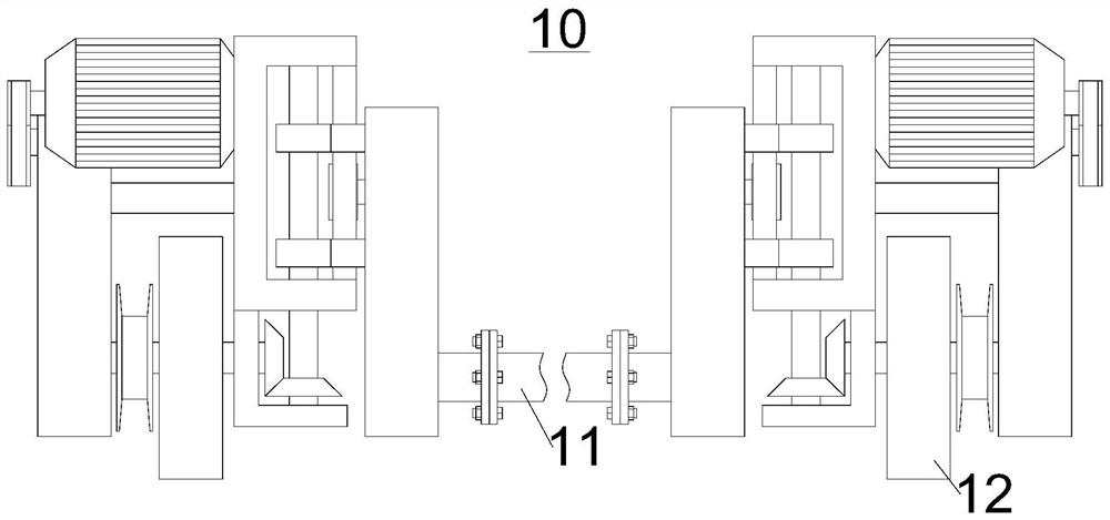
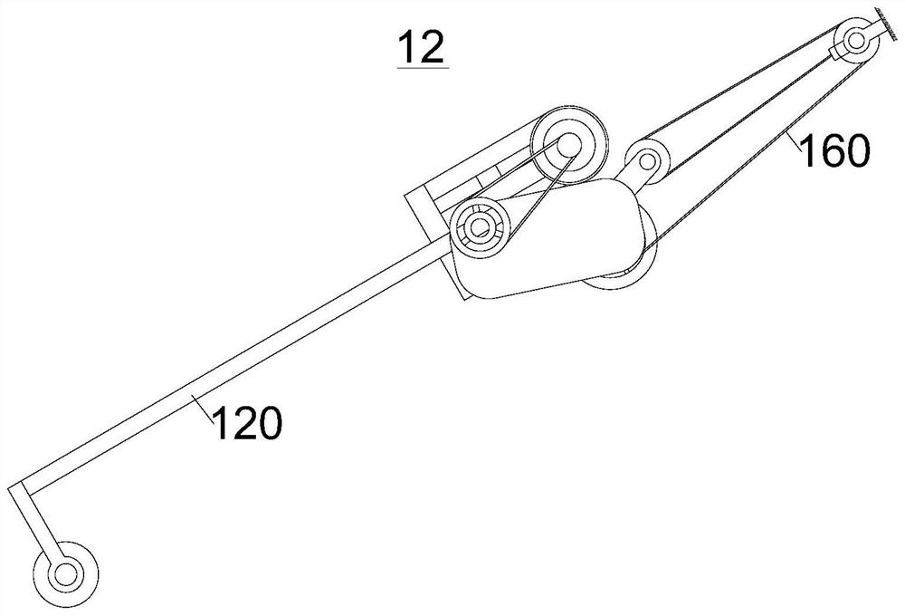
Greenhouse roller shutter robot and greenhouse roller shutter device

A robot and roller blind technology, which is applied in greenhouse cultivation, climate change adaptation, gardening, etc., can solve the problems of roller blind damage, out-of-synchronization of walking wheels, and difficulty in matching, so as to reduce the burden, make the walking parts consistent, and not easy to bend Effect

Pending Publication Date: 2021-02-26
电子科技大学成都学院
View PDF7 Cites 0 Cited by
  • Summary
  • Abstract
  • Description
  • Claims
  • Application Information

AI Technical Summary

Problems solved by technology

[0003] The existing greenhouse rolling robot usually includes a frame and a walking part, and the rolling rod and the walking wheel of the walking part are coaxially arranged. In the actual rolling process, one of the following two methods is usually used: the first Method: the walking wheel is on the ground, the roller blind is suspended in the air, and the traveling wheel and the rolling rod are driven by the motor at the same time, the height of the rolling rod must be greater than the maximum radius when the roller blind is rolled up, which will cause the rolling rod to be suspended in the air, and the rolling rod will be bent. Moreover, when using this method, two motors need to be used. This is because the travel distance of the rolling rod is different when it rotates a circle at different positions, and it is not synchronized with the road wheel, so it is difficult to match; the second method: the road wheel is suspended, the winding rod When the curtain is on the ground and only the roller rod is driven by the motor, the greenhouse roller blind not only has to bear the weight of the roller blind, but also bears the weight of the greenhouse roller blind robot, which will cause damage to the roller blind. This method is usually used in the prior art
Of course, the walking wheel rotates freely and the roller blind is suspended in the air, that is, the motor only drives the roller blind to rotate, which belongs to the deformation of the second method, and has the disadvantages of the above two methods at the same time

Method used


Image

  • Greenhouse roller shutter robot and greenhouse roller shutter device
  • Greenhouse roller shutter robot and greenhouse roller shutter device
  • Greenhouse roller shutter robot and greenhouse roller shutter device

Examples


Embodiment Construction

[0034] In order to make the purpose, technical solutions and advantages of the embodiments of the present invention clearer, the technical solutions in the embodiments of the present invention will be clearly and completely described below in conjunction with the drawings in the embodiments of the present invention. Obviously, the described embodiments It is a part of embodiments of the present invention, but not all embodiments. The components of the embodiments of the invention generally described and illustrated in the figures herein may be arranged and designed in a variety of different configurations.

[0035] Accordingly, the following detailed description of the embodiments of the invention provided in the accompanying drawings is not intended to limit the scope of the claimed invention, but merely represents selected embodiments of the invention. Based on the embodiments of the present invention, all other embodiments obtained by persons of ordinary skill in the art wi...


PUM


Abstract

The invention relates to a greenhouse roller shutter robot and a greenhouse roller shutter device, and belongs to the technical field of facility agriculture. The greenhouse roller shutter device comprises a rolling rod and the greenhouse roller shutter robot, the greenhouse roller shutter robot comprises a roller shutter vehicle, the roller shutter vehicle comprises a machine frame, walking partsand a roller shutter frame, the walking parts are arranged at the two ends of the machine frame, the roller shutter frame is arranged on the machine frame, the roller shutter frame is provided with an output shaft used for being connected to the rolling rod, the roller shutter vehicle has the working state that the machine frame advances and the roller shutter frame ascends or descends, the ascending and descending speed of the roller shutter frame is gradually decreased from bottom to top, and the rotating speed of the output shaft is gradually decreased from bottom to top. According to thegreenhouse roller shutter robot and the greenhouse roller shutter device, the greenhouse roller shutter robot adopts a mode that walking wheels touch the ground, the burden of a roller shutter is reduced, on this basis, the rolling rod ascends gradually, the roller shutter outside the rolling rod is close to or makes contact with a greenhouse ceiling all the time, pressure applied to the rolling rod is small, it is effectively guaranteed that the rolling rod is not liable to be bent, in addition, the rotating speed of the output end of the rolling rod is gradually decreased from bottom to top,and the advancing speed of the rolling rod is consistent with that of the walking parts.

Description

technical field [0001] The invention belongs to the technical field of facility agriculture, and in particular relates to a greenhouse rolling robot and a greenhouse rolling device. Background technique [0002] In the field of facility agriculture, the greenhouse is an indispensable part, and the greenhouse can keep agricultural products in a relatively closed growth environment. Usually, the roof of the greenhouse needs to be equipped with roller blinds, so as to ensure the light intensity and heat preservation in the greenhouse. [0003] The existing greenhouse rolling robot usually includes a frame and a walking part, and the rolling rod and the walking wheel of the walking part are coaxially arranged. In the actual rolling process, one of the following two methods is usually used: the first Method: the walking wheel is on the ground, the roller blind is suspended in the air, and the traveling wheel and the rolling rod are driven by the motor at the same time, the heigh...

Claims


Application Information

Patent Timeline
Patent Type & Authority Applications(China)
IPC IPC(8): A01G9/22
CPCA01G9/227Y02A40/25
Inventor 王旭聂小燕
Owner 电子科技大学成都学院
Why Eureka
Try Eureka