Industrial metal ring pressing machine

A ring press, industrial technology, used in metal processing equipment, manufacturing tools, feeding devices, etc., can solve problems such as inconsistent diameters, and achieve good stamping effects

Pending Publication Date: 2021-02-26
邓宝富
View PDF6 Cites 4 Cited by
  • Summary
  • Abstract
  • Description
  • Claims
  • Application Information

AI Technical Summary

Problems solved by technology

[0005] In order to overcome the shortcomings of the existing technology that the diameters of some rings are inconsistent, requiring personnel to carry out frequent measurements and difficult operations, an industrial metal pressure ring with simple operation, high molding quality and consistent molding standards is provided. machine

Method used


Image

  • Industrial metal ring pressing machine
  • Industrial metal ring pressing machine
  • Industrial metal ring pressing machine

Examples


Embodiment 1

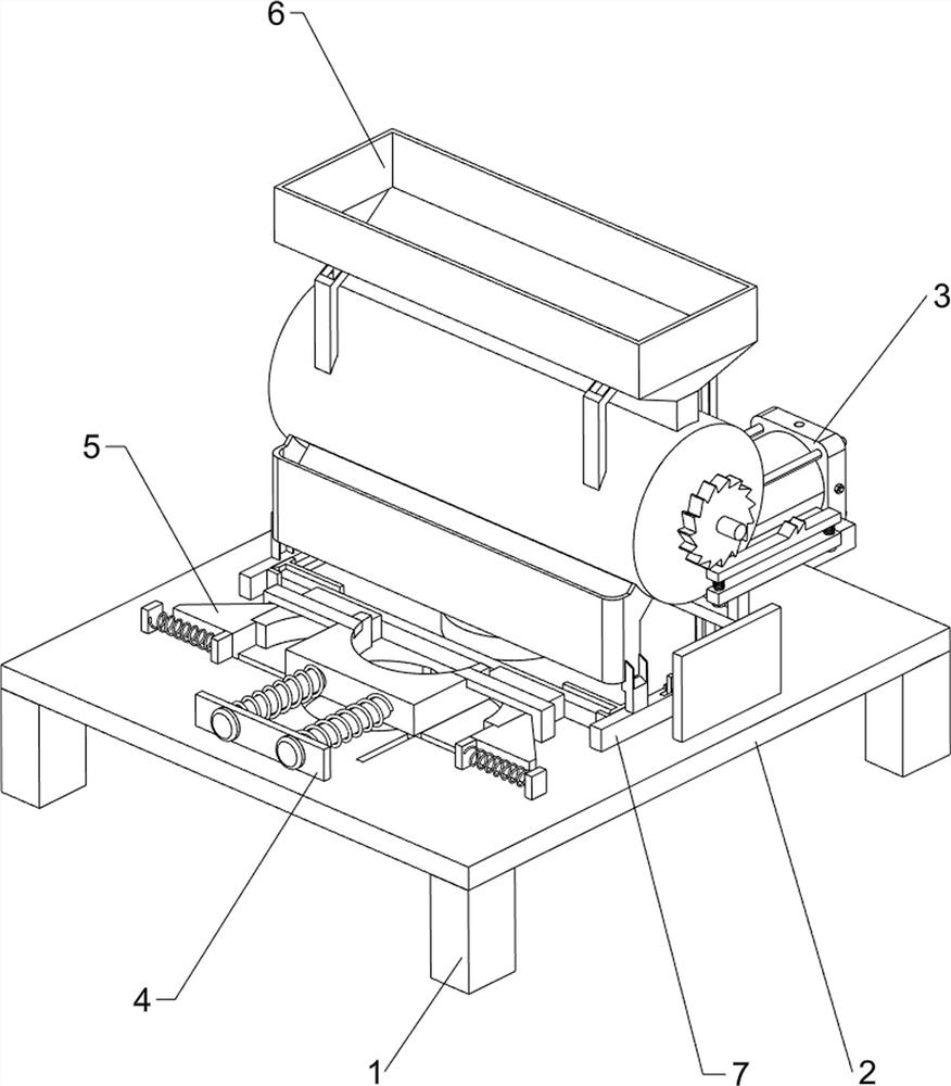
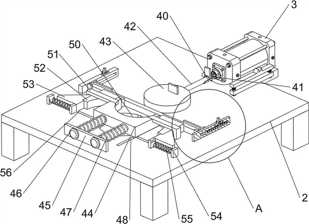
[0023] A metal ring press machine for industrial use, such as Figure 1-2 As shown, it includes support 1, workbench 2, cylinder 3, stamping mechanism 4 and pressure ring mechanism 5, workbench 2 is arranged between the top of support 1, the number of support 1 is 4, and the right side of workbench 2 is provided with The cylinder 3 is provided with a stamping mechanism 4 on the left side of the top of the workbench 2, and a pressing ring mechanism 5 is provided on the left side of the top of the workbench 2.

[0024] When people need to use this machine, first people place the metal bar on the top of the workbench 2 between the stamping mechanism 4, and then start the cylinder 3 to make the telescopic rod of the cylinder 3 move to the left, and the telescopic rod of the cylinder 3 drives the stamping mechanism 4 Move to the left to stamp the metal strip, and then punch the middle part of the metal strip into a semicircle, then the stamping mechanism 4 continues to move to the ...

Embodiment 2

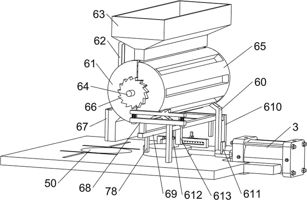
[0030] On the basis of Example 1, such as Figure 3-4As shown, it also includes a blanking mechanism 6. The blanking mechanism 6 includes a first pole 60, a roller 61, a second pole 62, a hopper 63, a first rotating shaft 64, a roller 65, a ratchet gear 66, an unloading Material port 67, ratchet rack 68, moving rod 69, guide block 610, first contact block 611, second contact block 612 and first contact rod 613, the top right side of workbench 2 is symmetrically provided with first support rod 60 A roller 61 is arranged between the first poles 60, a second pole 62 is arranged symmetrically on the left and right sides of the roller 61, a hopper 63 is arranged between the second poles 62, and a second A rotating shaft 64, the first rotating shaft 64 is provided with a roller 65, the roller 65 is located inside the roller 61, the front end of the first rotating shaft 64 is provided with a ratchet gear 66, the left side of the roller 61 is provided with a discharge port 67, and the...


PUM


Abstract

The invention relates to a metal ring pressing machine, in particular to an industrial metal ring pressing machine. The industrial metal ring pressing machine is easy to operate, high in forming quality and consistent in forming standard. The industrial metal ring pressing machine comprises supports, an air cylinder, a stamping mechanism and a ring pressing mechanism, wherein a workbench is arranged between the tops of the supports; the air cylinder is arranged on the workbench; the stamping mechanism is arranged on the workbench; and the ring pressing mechanism is arranged on the workbench. By starting the air cylinder, left-right movement of a stamping block is achieved, and then under cooperation between the stamping mechanism and the ring pressing mechanism, metal rings which are consistent in standard and high in quality can be efficiently manufactured and machined; and a ratchet rack is driven to move left and right through left-right movement of a moving rod, and then intermittent discharging of metal strips is achieved.

Description

technical field [0001] The invention relates to a metal ring pressing machine, in particular to an industrial metal ring pressing machine. Background technique [0002] Metal rings are generally formed by stamping metal strips. Nowadays, with the continuous improvement of people's science and technology, the functions of mechanical equipment are also constantly updated. At present, people mostly use mechanical equipment to press metal strips. [0003] In the ring pressing process, the corresponding mechanical arm is mainly used for pressing and forming. This operation is more flexible, but the disadvantage is that in the ring pressing process, the diameter of some rings will be inconsistent, requiring frequent measurement by personnel. , is more troublesome, not only increases the labor intensity of the staff, but also reduces the quality of the forming ring, and the use of the mechanical arm to press the forming is more difficult to operate. [0004] Therefore, in view of ...

Claims


Application Information

Patent Timeline
Patent Type & Authority Applications(China)
IPC IPC(8): B21D7/022B21D43/00B21D43/14
CPCB21D7/022B21D43/003B21D43/14
Inventor 不公告发明人
Owner 邓宝富
Why Eureka
Try Eureka