Industrial iron sheet punch forming equipment

A technology of stamping forming and industrial use, which is applied in the field of stamping and forming equipment for industrial iron sheets, which can solve the problems of inconvenient collection of iron sheets and achieve the effect of convenient collection

Inactive Publication Date: 2021-02-26
赵勇
View PDF0 Cites 4 Cited by
  • Summary
  • Abstract
  • Description
  • Claims
  • Application Information

AI Technical Summary

Problems solved by technology

[0005] In order to overcome the shortcomings of the existing iron sheet stamping and forming method that the iron sheet needs to be manually pushed for blanking and the collection of the stamped and formed iron sheet is inconvenient, the technical problem to be solved is: to provide a method that can automatically unload the iron sheet Industrial iron sheet stamping and forming equipment that pushes out stamped and formed iron sheets and facilitates the collection of stamped and formed iron sheets

Method used


Image

  • Industrial iron sheet punch forming equipment
  • Industrial iron sheet punch forming equipment
  • Industrial iron sheet punch forming equipment

Examples


Embodiment 1

[0025] An industrial stamping and forming equipment for iron sheets, such as figure 1 As shown, it includes a base 1, a bracket 2, a servo motor 3, a stamping mechanism 4, a propulsion mechanism 5, and a discharge mechanism 6. A bracket 2 is provided on the front side of the top of the base 1, and a servo motor 3 is provided on the top right side of the rear side of the bracket 2. , a stamping mechanism 4 is arranged in the middle of the top of the rear side of the bracket 2, and the parts of the stamping mechanism 4 are connected with the output shaft of the servo motor 3; Connected, base 1 top rear side is provided with discharging mechanism 6, and the parts of discharging mechanism 6 are connected with the parts of propulsion mechanism 5.

[0026] When people need to press and form the iron sheet, people first place the iron sheet on the parts of the stamping mechanism 4, and then people start the servo motor 3 again, and the rotation of the output shaft of the servo motor ...

Embodiment 2

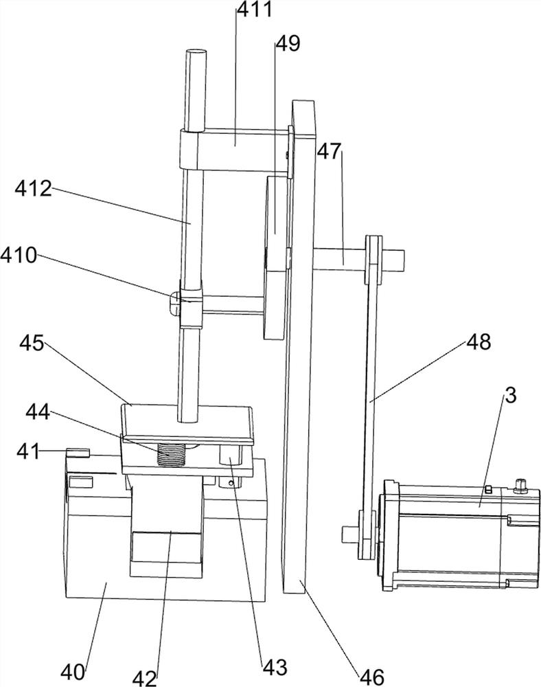
[0028] On the basis of Example 1, such as figure 2 and image 3As shown, the stamping mechanism 4 includes a workbench 40, a first block 41, a punch 42, a first connecting rod 43, a first spring 44, a connecting plate 45, a first supporting plate 46, a first rotating rod 47, a first A belt pulley assembly 48, rotating disk 49, the first push block 410, the first fixed block 411 and the second connecting rod 412, a workbench 40 is arranged in the middle of the top of the rear side of the support 2, and the front and rear sides of the top of the left side of the workbench 40 are all provided with There is a first block 41, a first support plate 46 is arranged in the middle of the top of the rear side of the support 2, the first support plate 46 is located on the right side of the workbench 40, and the upper side of the first support plate 46 is rotatably connected with a first rotating rod 47 The first pulley assembly 48 is connected between the right side of the first rotatin...

Embodiment 3

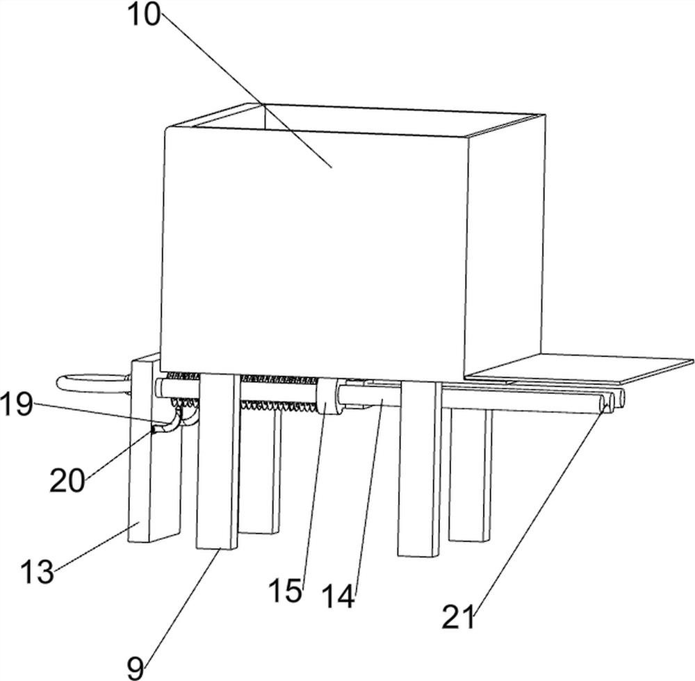
[0033] On the basis of Example 2, such as Figure 4-7 As shown, the discharge mechanism 6 includes a first support rod 60, a storage bucket 61, a second rotating shaft 62, a rotating block 63, a third fixed block 64, a third rotating rod 65, a second bevel gear set 66 and a third Pulley assembly 67, base 1 top, front, rear, left and right four sides are all provided with first support bar 60, is connected with storage barrel 61 between the tops of first support bar 60, and storage barrel 61 middle part is connected with second rotating shaft 62 in a rotational manner, the second The upper part of the rotating shaft 62 is provided with a rotating block 63, and the rotating block 63 is slidably connected with the bottom of the inner wall of the storage bucket 61. The right side of the rear part of the bracket 2 is provided with a third fixed block 64, and the middle part of the third fixed block 64 is rotatably connected with a third rotating block. Rod 65, the second bevel gear...


PUM


Abstract

The invention relates to iron sheet punch forming equipment, in particular to industrial iron sheet punch forming equipment. By means of the industrial iron sheet punch forming equipment, automatic discharging of iron sheets can be achieved, the iron sheets subjected to punch forming are pushed out, and the iron sheets subjected to punch forming can be collected conveniently. The industrial iron sheet punch forming equipment comprises a base, a support, a servo motor, a punching mechanism, a pushing mechanism and a discharging mechanism; the support is arranged at one side of the top of the base; the servo motor is arranged at one side of the top of the support; the punching mechanism is arranged at the side, close to the servo motor, of the top of the support; the pushing mechanism is arranged at the front side of the top of the support; and the discharging mechanism is arranged at the other side of the top of the base. Under the cooperation of the servo motor, the punching mechanism,the pushing mechanism, the discharging mechanism, a sliding rail and a storage box, the industrial iron sheet punch forming equipment has the advantages that automatic discharging of the iron sheetscan be carried out, punching forming is conducted on the iron sheets, the punched iron sheets are pushed out, and people can conveniently collect the punched iron sheets.

Description

technical field [0001] The invention relates to an iron sheet stamping forming equipment, in particular to an industrial iron sheet stamping forming equipment. Background technique [0002] Iron sheets are commonly used parts in the industry. People generally need to stamp and form the iron sheets before putting them into use. [0003] The existing stamping and forming methods for iron sheets are generally manual stamping and forming of the iron sheets by manually operating the stamping device. First, people start the stamping device, and then push the iron sheet to move to the bottom of the stamping device. People collect the iron sheets that have been stamped and formed again. The method for stamping and forming the iron sheets is cumbersome, and it is necessary to manually promote the iron sheets to move gradually, and it is inconvenient to collect the stamped and formed iron sheets. [0004] Therefore, it is necessary to develop a kind of industrial iron sheet stamping ...

Claims


Application Information

Patent Timeline
Patent Type & Authority Applications(China)
IPC IPC(8): B21D22/02B21D45/04B21D43/22B21D43/24
CPCB21D22/02B21D43/22B21D43/24B21D45/04
Inventor 赵勇
Owner 赵勇
Why Eureka
Try Eureka