Wireless control charging type electric tool

A technology of electric tools and wireless control, applied in manufacturing tools, portable drilling rigs, metal processing equipment, etc., can solve the problems of harming children and being easily used by children to play

Inactive Publication Date: 2021-02-26
西安致开工业自动化工程有限公司
View PDF1 Cites 0 Cited by
  • Summary
  • Abstract
  • Description
  • Claims
  • Application Information

AI Technical Summary

Problems solved by technology

[0005] The purpose of the present invention is to solve the problem that the existing rechargeable electric tools are easy to be used by children to play without the care of the guardian, and the problem of harming children after starting the tool is proposed, and a wireless control rechargeable electric tool is proposed.

Method used


Image

  • Wireless control charging type electric tool
  • Wireless control charging type electric tool

Examples


Embodiment 1

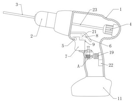
[0023] Example 1 as Figure 1-2 As shown, this wirelessly controllable rechargeable electric tool includes a housing 1, a rotary chuck 2 and a drill bit 3. The right inner wall of the housing 1 is fixed with a first motor 4, and the output end of the first motor 4 is rotated. There is a first rotating shaft 23, and the end of the first rotating shaft 23 away from the first motor 4 is rotatably connected to the end of the rotary chuck 2. The left inner wall of the housing 1 is fixedly connected with a fixed bent plate 6, and a fixed bent plate 6 is provided below the fixed bent plate 6. The trigger 7 has a through hole on the left side of the trigger 7, and a second rotating shaft 5 is rotated in the through hole. The lower surface of 6 is fixedly connected with an elastic device, the lower surface of the bent plate is located on the right side of the elastic device, and a switch button 8 is provided, and the right side of the trigger 7 is provided with an impact block 9, and t...

Embodiment 2

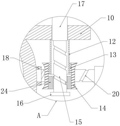
[0024] Embodiment 2 is on the basis of embodiment 1 such as figure 2 As shown, its trigger limit mechanism includes a turbine 14 and a connecting pipe 12, the inner part of the upper half of the turbine 14 is fixedly sleeved with a first bearing 13, and the inside of the first bearing 13 is fixedly sleeved with the outside of the connecting pipe 12, The interior of the lower half of the turbine 14 is fixedly sleeved with an internally threaded pipe 24, the interior of the internally threaded pipe 24 is provided with a screw mandrel 15, the bottom end of the screw mandrel 15 is fixedly provided with a limit block 16, and the top end of the screw mandrel 15 is fixedly provided with a The square rod 17, the left inner wall of the housing 1 is fixedly provided with the second bearing 18 below the connecting pipe 12, and the second motor 19 is fixedly arranged on the right inner wall of the housing 1 corresponding to the second bearing 18. The output end of the second motor 19 and...

Embodiment 3

[0025] Embodiment 3 is such as on the basis of embodiment 1 figure 1 As shown, its elastic device is a compression spring 21, and after the trigger 7 is pulled, the compression spring can reset the trigger 7.


PUM


Abstract

The invention relates to the technical field of electric tools, and discloses a wireless control charging type electric tool. The tool comprises a shell, a rotating chuck and a drill bit, wherein a first motor is fixedly arranged on the right inner side wall of the shell, a first rotating shaft is rotatably arranged at an output end of the first motor, the end, away from the first motor, of the first rotating shaft is rotatably connected to the tail end of the rotating chuck, and a fixed bent plate is fixedly connected to the left inner side wall of the shell. According to the tool, the rechargeable electric tool can be remotely locked, so that children are prevented from hurting themselves due to playing of the electric tool when guardians are not around.

Description

technical field [0001] The invention relates to the technical field of electric tools, in particular to a wirelessly controllable rechargeable electric tool. Background technique [0002] In the 1960s, with the development of battery manufacturing technology, battery-type power tools without power cords that used nickel-cadmium batteries as power sources appeared. There are many kinds of tools, such as electric drills, electric screwdrivers, electric wrenches and electric grinders, etc. [0003] Among them, the patent number is CN205810874U, which discloses a rechargeable electric tool, which includes a main body of the electric tool, a battery pack and a connector. The main body of the electric tool is plugged into the main body connecting seat and electrically connected with the main body connecting seat, and the battery pack is plugged into the battery pack connecting seat and electrically connected with the battery pack connecting seat, but the technical solution Still...

Claims


Application Information

Patent Timeline
Patent Type & Authority Applications(China)
IPC IPC(8): B23B45/02
CPCB23B45/02
Inventor 白琳
Owner 西安致开工业自动化工程有限公司
Why Eureka
Try Eureka