
High-precision circular knitting machine part production process

A production process and circular knitting machine technology, applied in the production process of high-precision circular knitting machine accessories, can solve problems such as many loop forming systems, environmental protection, and scrapped needle cylinders

Active Publication Date: 2021-02-26
漳州市永良针纺机械有限公司
View PDF14 Cites 1 Cited by
  • Summary
  • Abstract
  • Description
  • Claims
  • Application Information

AI Technical Summary

Problems solved by technology

[0002] Large circular knitting machines are widely used in the existing knitting machines. Large circular knitting machines have many knitting systems, high speed, high output, pattern change block, good fabric quality, less process, and strong product adaptability, so they develop rapidly. The needle cylinder in the large circular knitting machine is a very important accessory. The function of the needle cylinder is mainly to fix the knitting needles for the large circular knitting machine and drive the knitting needles to work; Needle grooves are cut on the surface, because large circular knitting machines have high requirements on the accuracy of the needle grooves, often in the process of cutting needle grooves, slight vibrations may lead to the scrapping of the entire needle cylinder, and if the existing needle cylinder is in use If the wear of individual needle grooves is serious, the entire needle cylinder needs to be replaced, which is not environmentally friendly.

Method used


Image

  • High-precision circular knitting machine part production process
  • High-precision circular knitting machine part production process
  • High-precision circular knitting machine part production process

Examples


Embodiment Construction

[0040] In order to further explain the technical solution of the present invention, the present invention will be described in detail below through specific examples.

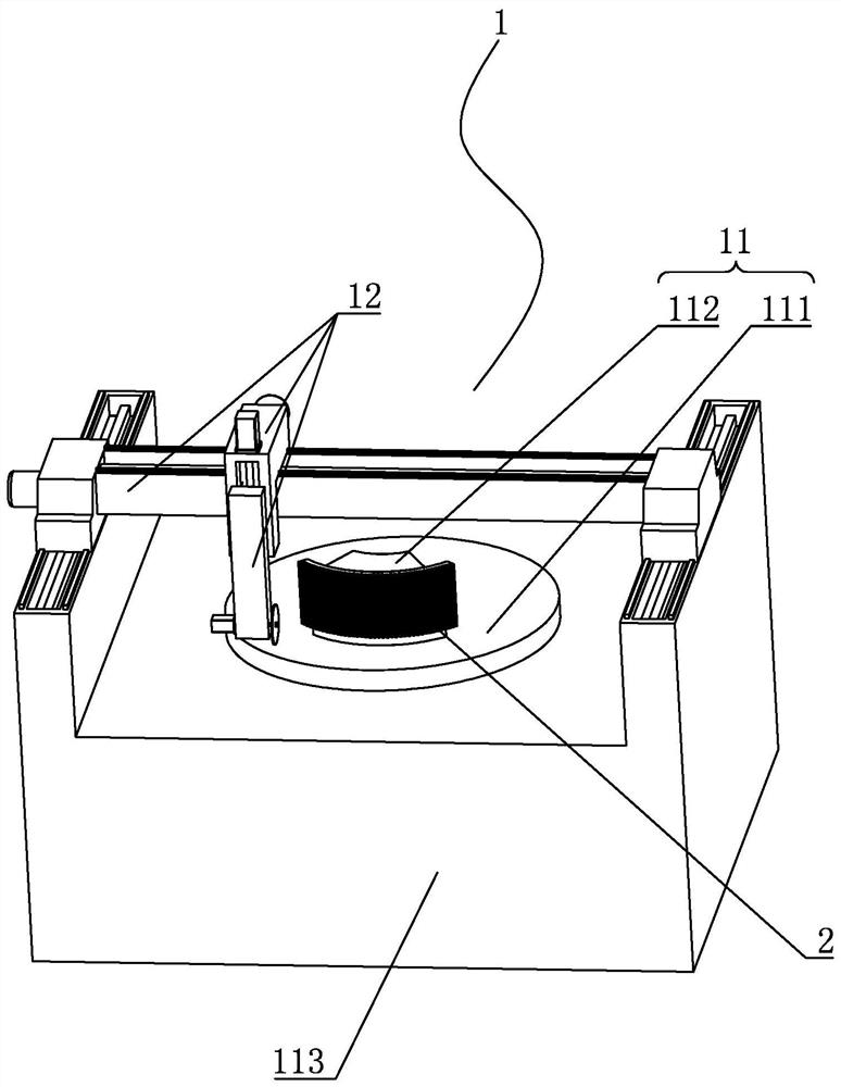
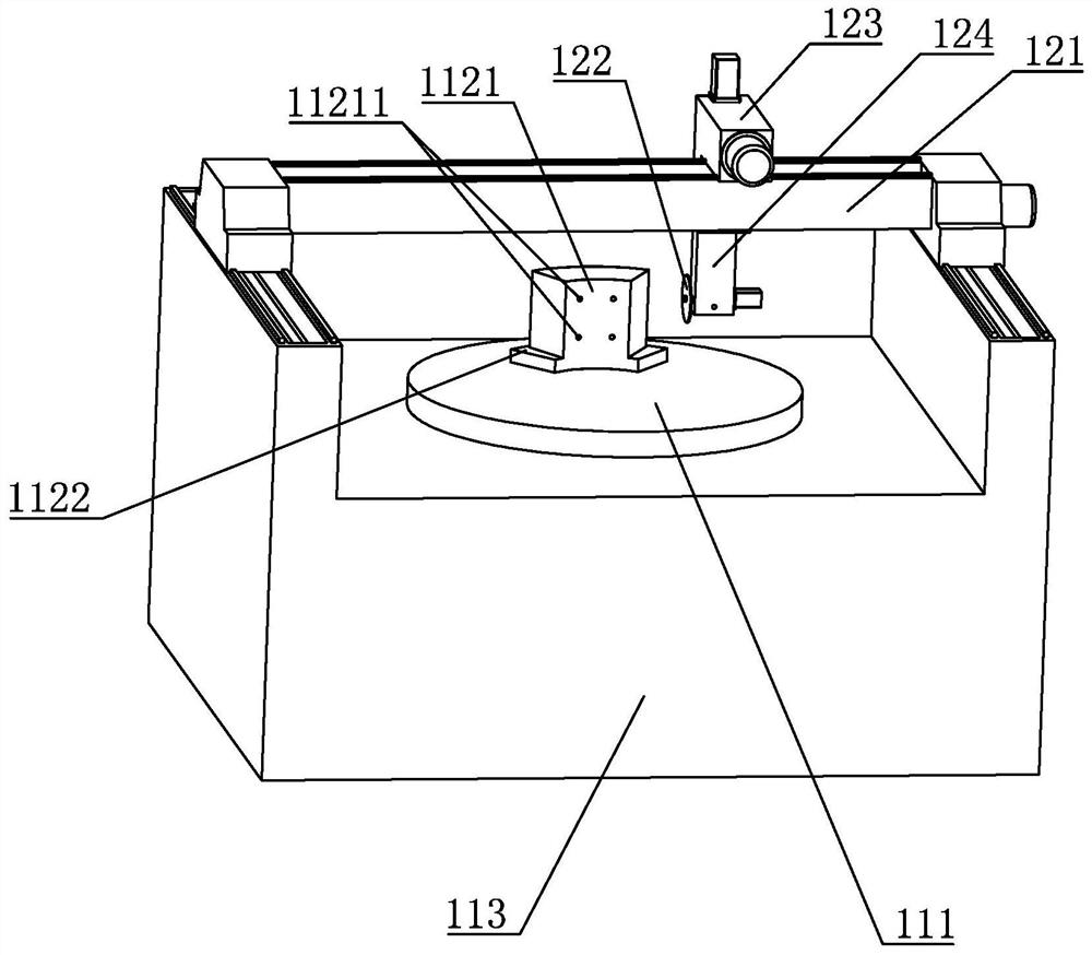
[0041] Such as Figure 1 to Figure 6 Shown, it is a kind of high-precision circular weft knitting machine accessory production process that the present invention relates to, comprises the following steps:

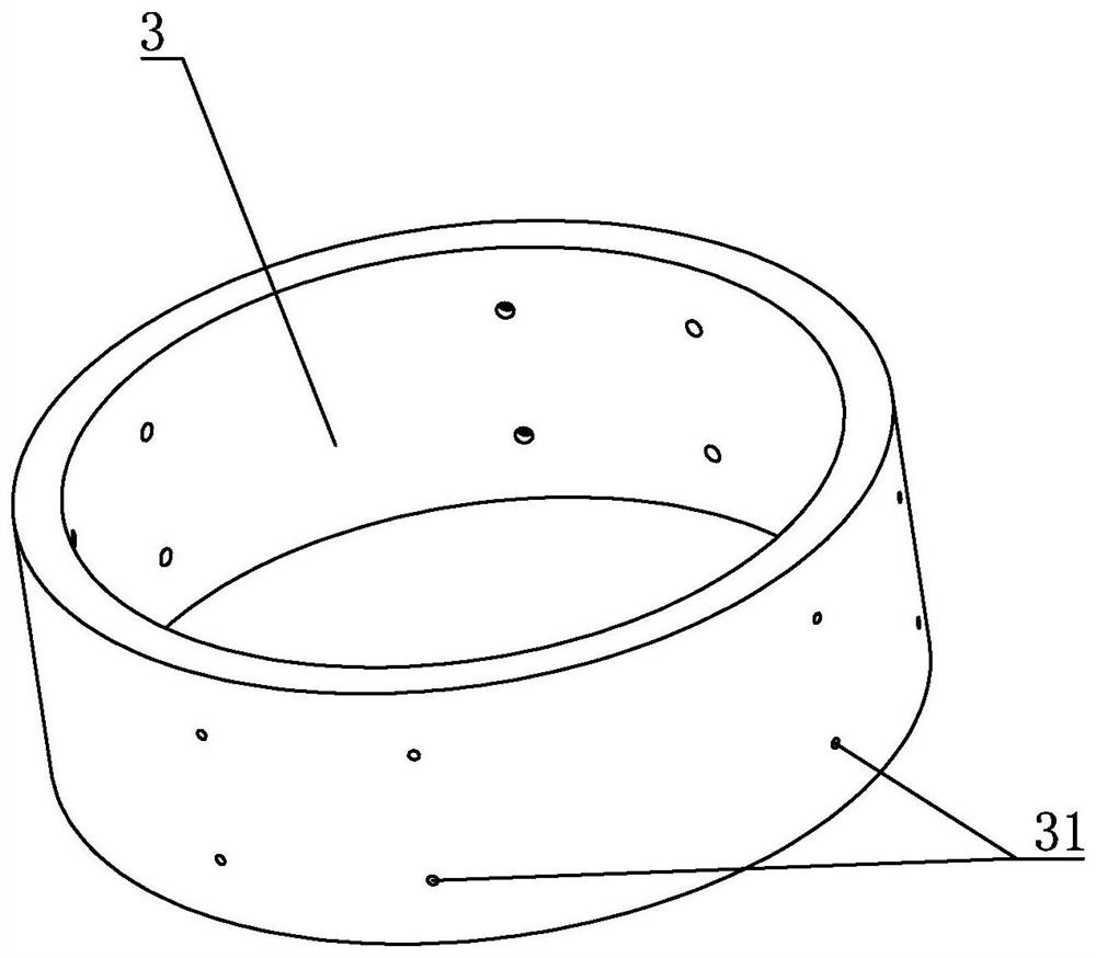
[0042] (1) Process an inner syringe blank 3 and a plurality of outer syringe blanks 2 that can be fixed and are covered with the outer wall of the inner syringe blank 3;

[0043] (2) Process a threaded hole on the inner wall of the outer syringe blank 2, and process a connecting hole 31 corresponding to the threaded hole in the inner syringe blank 3; the threaded connection is more reliable; the connecting hole 31 includes a connecting portion and a countersink part, the diameter of the countersunk head is larger than the diameter of the connecting part and the countersunk head is close to the inner wall of...


PUM


Abstract

The invention discloses a high-precision circular knitting machine part production process. The production process comprises the following steps that an inner needle cylinder blank and a plurality ofouter needle cylinder blanks which can be fixed and are fully distributed on the outer side wall of the inner needle cylinder blank are machined; threaded holes are machined in the inner side walls ofthe outer needle cylinder blanks, and connecting holes corresponding to the threaded holes are machined in the inner needle cylinder blank; the outer needle cylinder blanks are fixed; the outer sidewalls of the outer needle cylinder blanks are machined until the outer side walls of the outer needle cylinder blanks are full of needle grooves; and the plurality of machined outer needle cylinder blanks are fixedly connected to the inner needle cylinder blank together to form a needle cylinder. Through the process, the needle cylinder is machined, when the needle grooves in the outer surface ofthe needle cylinder are damaged in the working process, the outer needle cylinder blanks can be replaced according to the damaged positions, the whole needle cylinder does not need to be abandoned, and environmental protection and reliability are better achieved; and during machining, the situation that the whole needle cylinder fails to be machined and is abandoned due to the fact that errors occur in machining of a certain needle groove is avoided, and the machining error-tolerant rate is high.

Description

technical field [0001] The invention relates to the field of knitting machinery, in particular to a production process for accessories of a high-precision circular weft machine. Background technique [0002] Large circular knitting machines are widely used in the existing knitting machines. Large circular knitting machines have many knitting systems, high speed, high output, pattern change block, good fabric quality, less process, and strong product adaptability, so they develop rapidly. The needle cylinder in the large circular knitting machine is a very important accessory. The function of the needle cylinder is mainly to fix the knitting needles for the large circular knitting machine and drive the knitting needles to work; Needle grooves are cut on the surface, because large circular knitting machines have high requirements on the accuracy of the needle grooves, often in the process of cutting needle grooves, slight vibrations may lead to the scrapping of the entire need...

Claims


Application Information

Patent Timeline
IPC IPC(8): B23D45/00B23D47/04B23D47/12
CPCB23D45/00B23D47/04B23D47/12
Inventor 李阿扁赖槿峰刘奇峰李俊聪
Owner 漳州市永良针纺机械有限公司
Learn More