
Method for removing pollutant granules in barrier layer and metal layer

A metal layer and barrier layer technology, which is applied in the field of removing pollutant particles in the barrier layer and metal layer, can solve the problems of PVD airtightness decrease, airtightness decrease, increase the production cost of semiconductor devices, etc., and achieve the effect of reducing production cost

Inactive Publication Date: 2015-01-28
SEMICON MFG INT (SHANGHAI) CORP +1
View PDF2 Cites 0 Cited by
  • Summary
  • Abstract
  • Description
  • Claims
  • Application Information

AI Technical Summary

Problems solved by technology

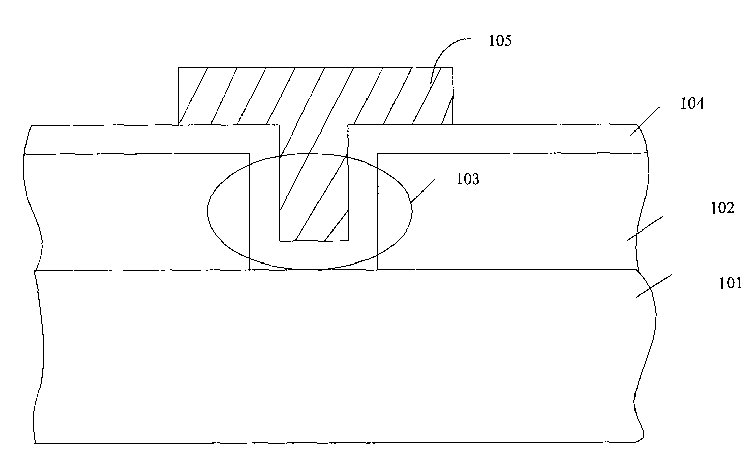
[0003] Theoretically speaking, the PVD reaction chamber should be a closed container. However, in practical applications, if the PVD reaction chamber is used for too long, the airtightness of the PVD reaction chamber will decrease, or due to misoperation, it may also cause PVD For these reasons, pollutant particles in the air may enter the PVD reaction chamber and be doped in the barrier layer 104 or the metal layer 105 with the deposition of the barrier layer 104 or the metal layer 105, thereby affecting the barrier layer 104 or the metal layer 105. layer 104 or metal layer 105 causing contamination that ultimately affects the performance of the semiconductor device
[0004] If the barrier layer or the metal layer is doped with pollutant particles, the final semiconductor device is regarded as a substandard product. Therefore, in the prior art, when the metal interconnection process is completed, the bright field scanning method (BFI) is used Detect the barrier layer and the metal layer. When it is detected that the barrier layer or the metal layer of the wafer is doped with pollutant particles, the wafer is scrapped. It can be seen that once the barrier layer or the metal layer of the wafer is doped with Contaminant particles, the wafer can only be scrapped, thus increasing the production cost of semiconductor devices

Method used


Image

  • Method for removing pollutant granules in barrier layer and metal layer
  • Method for removing pollutant granules in barrier layer and metal layer
  • Method for removing pollutant granules in barrier layer and metal layer

Examples


Embodiment Construction

[0033] In order to make the object, technical solution and advantages of the present invention clearer, the present invention will be further described in detail below with reference to the accompanying drawings and examples.

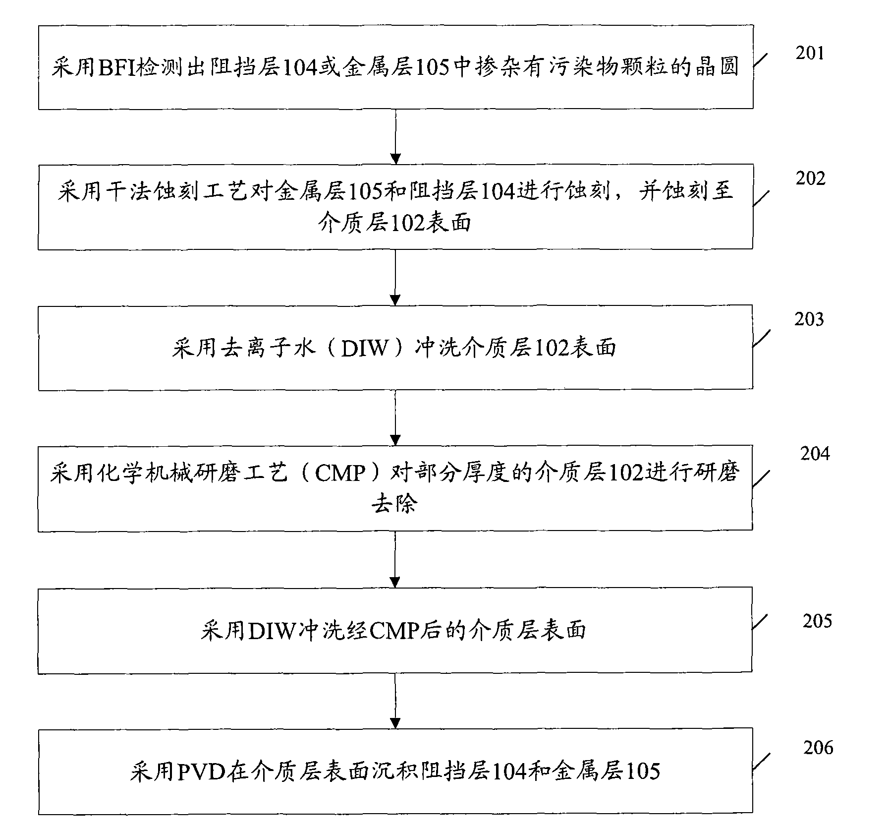
[0034] figure 2 A flowchart of an embodiment of a method for removing pollutant particles in a barrier layer and a metal layer provided by the present invention, such as figure 2 As shown, the method includes the following steps:

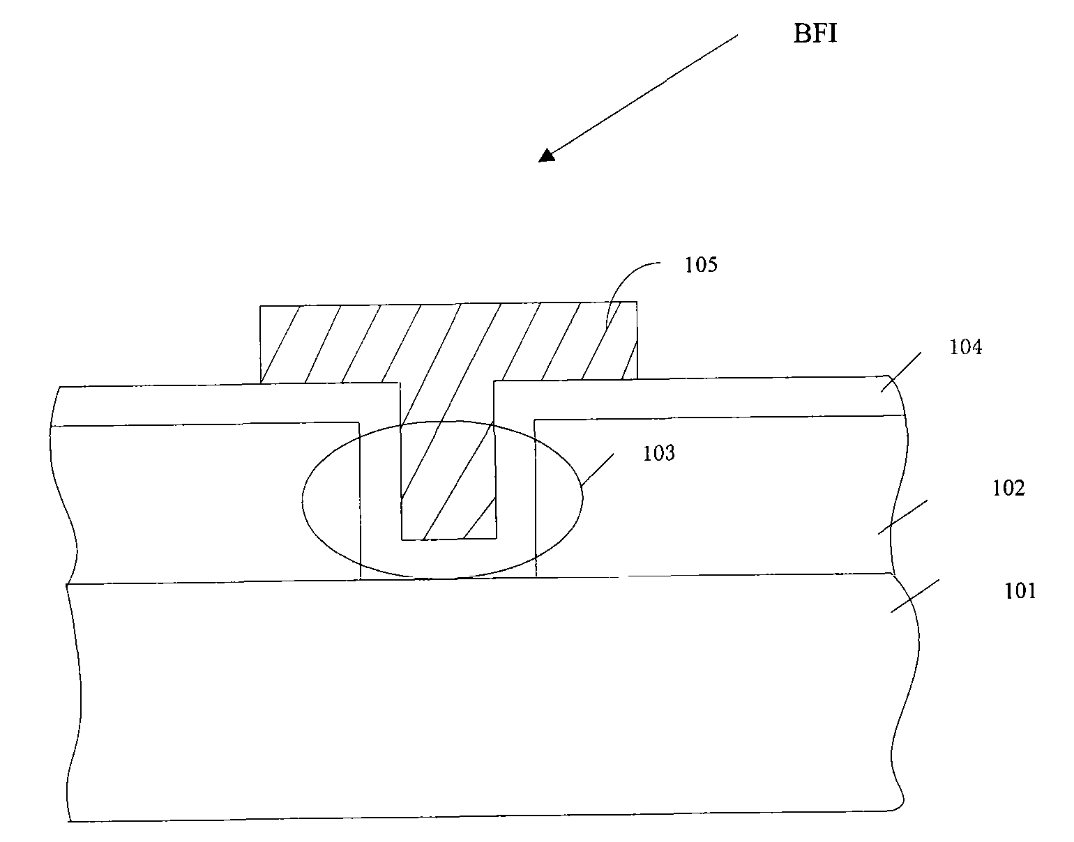
[0035] Step 201, image 3 It is a schematic cross-sectional view of the process structure of step 201 in a method for removing pollutant particles in the barrier layer and the metal layer provided by the present invention, as image 3 As shown, a wafer doped with contaminant particles in the barrier layer 104 or the metal layer 105 is detected by BFI.

[0036] BFI is an existing detection technology, image 3 , 4 , 5, 6, 7, 8, and 9 are marked as figure 1 description, which will not be repeated here.

[0037] Step 20...


PUM


Abstract

The invention discloses a method for removing pollutant granules in a barrier layer and a metal layer, comprising the following steps: etching a metal layer and a barrier layer which are doped with pollutant granules by a dry etching technique and etching to the surface of a dielectric layer; and milling and removing the partial thick dielectric layer by a chemical mechanical polishing process. By employing the method, the production cost of a semiconductor apparatus can be lowered.

Description

technical field [0001] The invention relates to the field of semiconductor manufacturing, in particular to a method for removing pollutant particles in barrier layers and metal layers. Background technique [0002] With the wide application of electronic devices, the manufacturing process of semiconductors has been developed rapidly. In the manufacturing process of semiconductors, metal interconnection processes are involved. figure 1 is a schematic cross-sectional view of the metal interconnection process structure, such as figure 1 As shown, a wafer is provided, and a dielectric layer 102 is deposited on a substrate 101 of the wafer. After an etching process is used to form grooves 103 on the dielectric layer 102, the wafer is placed in a physical vapor deposition process (PVD) reaction In the chamber, the barrier layer 104 and the metal layer 105 are deposited by PVD process, thus completing the metal interconnection process. [0003] Theoretically speaking, the PVD rea...

Claims


Application Information

Patent Timeline
Patent Type & Authority Patents(China)
IPC IPC(8): H01L21/3213H01L21/3105H01L21/311H01L21/768
Inventor 潘继岗彭澎
Owner SEMICON MFG INT (SHANGHAI) CORP
Learn More