
Heating line heater

A heating wire and heater technology, which is used in household heating, heating methods, electric heating systems, etc., can solve the problems of inability to use ordinary wood floor heating, waste of resources, waste boards, etc., to prevent misconnection and poor contact, Eliminate safety problems and secure wiring

Inactive Publication Date: 2015-04-29
欧邦智能家居(武汉)有限公司
View PDF5 Cites 0 Cited by
  • Summary
  • Abstract
  • Description
  • Claims
  • Application Information

AI Technical Summary

Problems solved by technology

[0003] Now there are many wooden floors on the market, most of them are wooden floors without heating function, and it is impossible to use this kind of ordinary wooden floor for heating
I once invented the heating laminated floor, the heating multi-layer solid wood heating floor. Although the above problems have been solved, the production process is too delicate. When the large board is pressed, the heating device is pressed into the designed floor. The design size is separated, and each heating floor has a heating function. This approach is equivalent to installing a branch circuit during the processing of wooden floors. Each branch circuit is distributed in a wooden floor. During the processing of the entire board In the process, these circuit branches need to be positioned accurately, otherwise the circuit may be cut off during the cutting process, resulting in circuit failure and waste boards
This processing method leads to higher cost of the product, which is not conducive to popularization
Furthermore, the heating device is suppressed in the wooden floor, if it is damaged, it cannot be replaced, and the whole heating floor can only be scrapped together, resulting in a waste of resources

Method used


Image

  • Heating line heater
  • Heating line heater

Examples


Embodiment 1

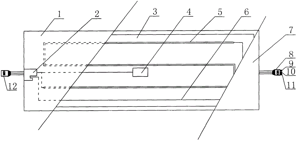
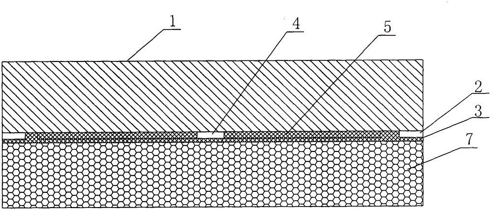
[0015] Example 1, such as figure 1 , 2 As shown, a heating wire heater includes a protective film 1, an aluminum foil 3, an insulation layer 7, a heating wire 5, a temperature switch 4 and a standard power wire for heating floors, and the heating wire 5 heater is arranged in sequence from top to bottom. There is a protective film 1, an aluminum foil 3 and an insulation layer 7; the heating wire 5 is arranged on the heat-sensitive adhesive on the surface of the aluminum foil 3, and a heating floor standard power line and a temperature switch 4 are arranged between the aluminum foil 3 and the insulation layer 7; The heating floor standard power cord is connected to the temperature switch 4 and the heating wire 5; the heating floor standard power cord includes insulating plugs at both ends, a power cord 6 in the middle, and a line card 2 located on the power cord 6; The left end of the heating floor standard power cord is a left insulating plug 12, the right end is a right insul...


PUM


Abstract

The invention discloses a heating line heater and belongs to the technical field of solid heating wooden floors. The heating line heater comprises a protection film, an aluminum foil, a thermal insulation layer, a heating line, a temperature switch and a heating floor standard power line. The heating line heater is sequentially provided with the protection film, the aluminum foil and the thermal insulation layer from top to bottom; the heating line is arranged on thermosensitive glue on the surface of the aluminum soil; the heating floor standard power line and the temperature switch are arranged between the aluminum soil and the thermal insulation layer; the heating floor standard power line is connected with the temperature switch and the heating line; the heating floor standard power line comprises insulating plugs at two ends, the power line in the middle and a line card which is arranged on the power line. The heating line heater has the advantages that the standard power line which is provided with the heating line is arranged on the back of the wood floor, a branch circuit is formed directly, the problem that the wooden floor machining process is complex is solved, the structure is simple, the utilization is simple, line connection is firm due to female and male insertion joint, error connection and poor contact are thoroughly avoided, and the safety problem is prevented.

Description

technical field [0001] The invention belongs to the technical field of solid wood heating floors, in particular to a heating wire heater. Background technique [0002] Our country has a vast territory, in which the temperature in the north is extremely low in winter, Northwest, Central China, East China and other regions have four distinct seasons, and the temperature is also below zero in winter. , large waste, serious pollution and other problems cannot be widely promoted and used, resulting in centralized heating only covering some extremely cold areas in the northern region and limited to some medium and large cities, while relatively small cities in the north and the vast majority of other cities are cold in winter The area cannot be heated at all. In recent years, the heating area is expanding: from the traditional north to the southern regions such as East China and Southwest China, and from large and medium-sized cities to small and medium-sized cities and vast town...

Claims


Application Information

Patent Timeline
Patent Type & Authority Applications(China)
IPC IPC(8): F24D13/00F24D19/10H01R13/64
Inventor 张正国
Owner 欧邦智能家居(武汉)有限公司
Learn More