
Chemical Vapor Deposition Chamber

A chemical vapor deposition and chamber technology, applied in the field of chemical vapor deposition chambers, can solve problems such as difficulty in controlling film formation uniformity, and achieve the effects of excellent film formation uniformity, lower operating costs, and convenient replacement and maintenance.

Active Publication Date: 2020-11-24
TCL CHINA STAR OPTOELECTRONICS TECH CO LTD
View PDF8 Cites 0 Cited by
  • Summary
  • Abstract
  • Description
  • Claims
  • Application Information

AI Technical Summary

Problems solved by technology

The film layer distribution prepared by using the existing chemical vapor deposition chamber is as follows: Figure 4 As shown, the color depth indicates the distribution of the film layer. As the panel manufacturing line is gradually upgraded from the original G2 generation to the G10.5 generation, it is difficult for the existing chemical vapor deposition chamber to control the uniformity of the film formation

Method used


Image

  • Chemical Vapor Deposition Chamber
  • Chemical Vapor Deposition Chamber
  • Chemical Vapor Deposition Chamber

Examples


Embodiment Construction

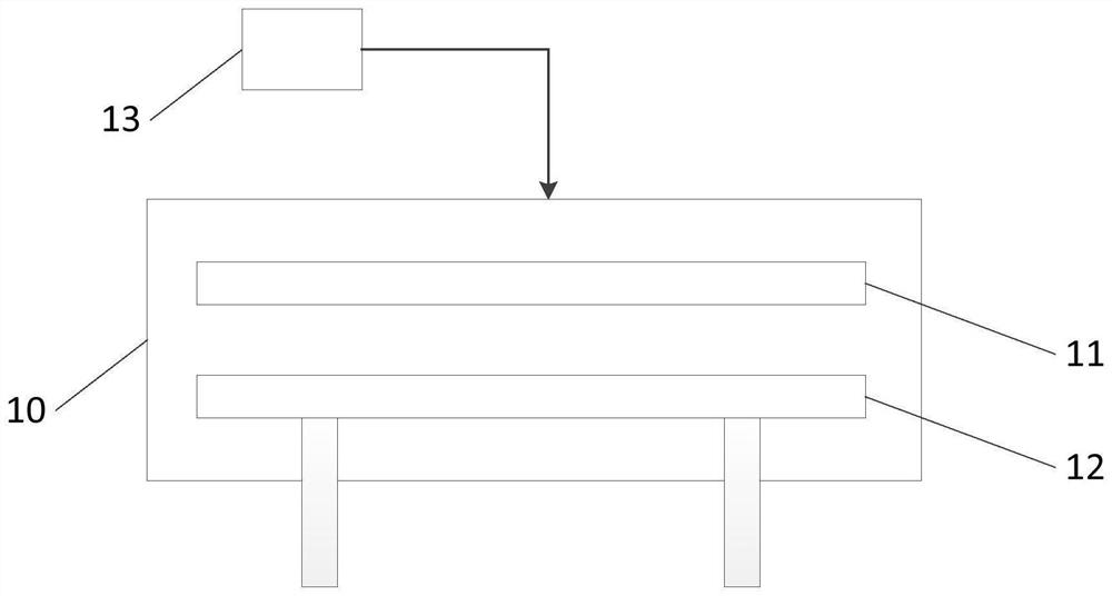
[0027] see Figure 5 , which is a schematic cross-sectional structure diagram of a preferred embodiment of the chemical vapor deposition chamber of the present invention, the chemical vapor deposition chamber of the present invention mainly includes a chamber 20, a diffusion plate 21 arranged on the upper part of the chamber 20, and the diffusion plate 21 mainly Used to make the process gas diffuse evenly, the heating plate 22 installed in the lower part of the chamber 20, the heating plate 22 is mainly used to carry the substrate during the film forming process, and communicate with the chamber 20 to deliver the gas source of the process gas to the chamber 20 23 , the top of the chamber 20 is provided with a gas delivery port to allow the process gas to enter the chamber 20 .

[0028] combine Figure 6 and Figure 7 , Figure 6 for Figure 5 Schematic top view of the diffuser plate and gas and RF delivery locations of the shown chemical vapor deposition chamber, Figure ...


PUM

PropertyMeasurementUnit
sizeaaaaaaaaaa

Abstract

The invention relates to a chemical vapor deposition cavity. The chemical vapor deposition cavity comprises a cavity body, a diffusion plate arranged on the upper portion in the cavity, a heating plate arranged on the lower portion in the cavity, and a gas source communicating with the cavity so as to convey process gas to the cavity; the diffusion plate is composed of multiple sub diffusion plates which are evenly distributed in an array manner, the heating plate is composed of multiple corresponding sub heating plates which are evenly distributed in an array manner, the cavity body is provided with multiple corresponding gas and radio frequency conveying positions so as to convey process gas and radio frequency at the corresponding position in the cavity body, and the center of the gas and radio frequency conveying position corresponds to the centers of the corresponding sub diffusion plates and the corresponding sub heating plates. Through the chemical vapor deposition cavity, filmforming uniformity is excellent, the process controllability and stability are improved, key parts of chemical vapor deposition are more convenient to replace and overhaul, after being partly damaged,the key parts of chemical vapor deposition can be replaced, whole scrapping is not needed, and operating cost is reduced.

Description

technical field [0001] The invention relates to the technical field of chemical vapor deposition, in particular to a chemical vapor deposition chamber. Background technique [0002] Chemical vapor deposition (Chemical vapor deposition, CVD for short) is a process technology in which reactant substances undergo chemical reactions under gaseous conditions to generate solid substances that are deposited on the surface of a heated solid substrate to obtain solid materials. The whole process can be realized by chemical vapor deposition device (referred to as CVD device). A CVD device generally includes a reaction chamber and a control device for controlling reaction conditions such as pressure and temperature inside the reaction chamber. [0003] Plasma-enhanced chemical vapor deposition (PECVD) is mainly used in the deposition of non-metallic thin films in industries such as liquid crystal TFT panel manufacturing, semiconductor chip manufacturing and solar cell manufacturing. ...

Claims


Application Information

Patent Timeline
Patent Type & Authority Patents(China)
IPC IPC(8): C23C16/455C23C16/46
CPCC23C16/455C23C16/46
Inventor 余华华
Owner TCL CHINA STAR OPTOELECTRONICS TECH CO LTD
Learn More