Hydraulic assembling device for hydraulic oil cylinder lug ring buffer sleeve

A technology of hydraulic cylinder and assembly device, applied in the field of hydraulic assembly, can solve the problems of inability to monitor assembly parameters at all times, and the assembly process cannot be automated, and achieves the effect of getting rid of high maintenance costs, improving equipment stability and simple operation.

Inactive Publication Date: 2021-02-26
娄底鼎力液压科技有限公司
View PDF0 Cites 0 Cited by
  • Summary
  • Abstract
  • Description
  • Claims
  • Application Information

AI Technical Summary

Problems solved by technology

[0004] The main purpose of the present invention is to provide a hydraulic assembly device for earring buffer sleeves of hydraulic cylinders, which can effectively solve the problems in the background art that the assembly process cannot be automated and cannot monitor assembly parameters at all times

Method used


Image

  • Hydraulic assembling device for hydraulic oil cylinder lug ring buffer sleeve
  • Hydraulic assembling device for hydraulic oil cylinder lug ring buffer sleeve
  • Hydraulic assembling device for hydraulic oil cylinder lug ring buffer sleeve

Examples


Embodiment 1

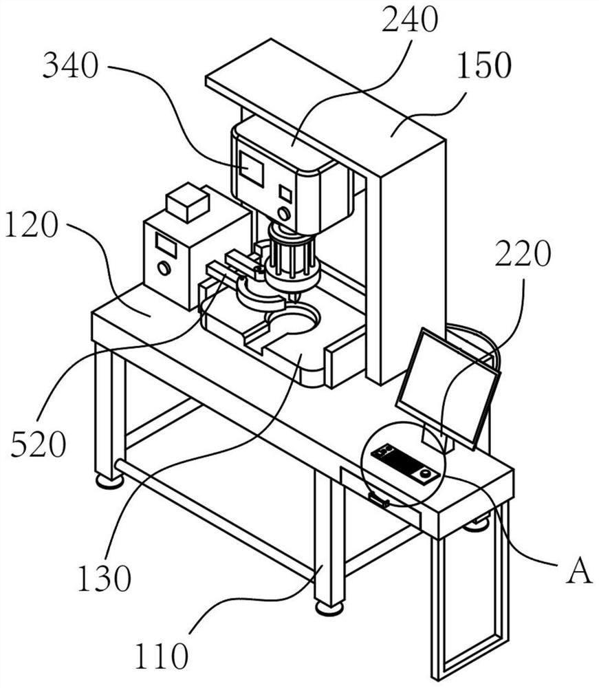
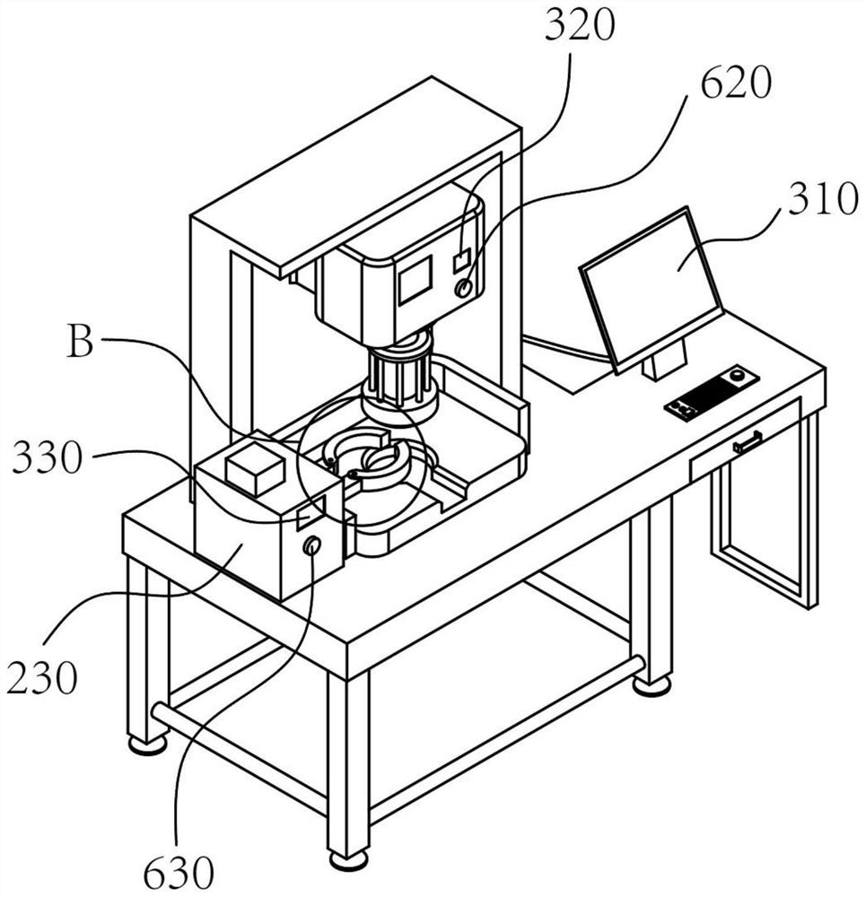
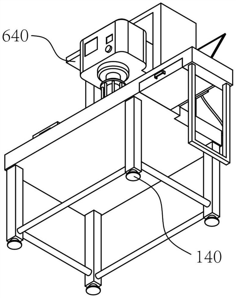
[0032] refer to figure 1—6. The present invention is a hydraulic assembly device for earring buffer sleeves of a hydraulic cylinder, including a support device 100, a control device 200, a monitoring device 300, a stamping device 400, a feeding device 500, and a safety device 600. The support device 100 includes equipment legs 110, working platform 120, workpiece positioning platform 130 and gantry 150, one end of several equipment legs 110 is welded to the surface of working platform 120, wherein, there are four equipment legs 110, which play the role of supporting and fixing, workpiece positioning platform One end of 130 is connected with one surface of working platform 120, one end of gantry frame 150 is connected with one surface of working platform 120, the control device 200 includes microcomputer control center 220, feeding system controller 230 and hydraulic controller 240, one end of microcomputer control center 220 is connected with One surface of the working platfor...

Embodiment 2

[0041] When personnel use it, place the workpiece to be processed firmly on the workpiece positioning platform 130, and execute the predetermined program by operating the main console 210, pushing the hydraulic press 420 to drive the hydraulic stamping shaft 430 to press the high-strength stamping head 410 to move the caliper 510 to the workpiece The tight workpiece is hydraulically assembled to complete one processing. It can cooperate with other equipment and accessories to build a fully automated work assembly line, which greatly improves work efficiency and equipment stability. Braking has the characteristics of simple operation, safety, high efficiency, and intelligence, and it gets rid of the cost of traditional manual processing and high maintenance.


PUM


Abstract

The invention discloses a hydraulic assembling device for a hydraulic oil cylinder lug ring buffer sleeve, and relates to the technical field of hydraulic assembly. The hydraulic assembling device comprises a supporting device, a control device, a monitoring device, a stamping device, a feeding device and a safety device, wherein the supporting device comprises device support legs, a working platform, a workpiece positioning platform and a portal frame, the control device comprises a microcomputer control center, a feeding system controller and a hydraulic controller, one end of the microcomputer control center is connected with one surface of the working platform, one end of the feeding system controller is connected with one surface of the working platform, and one end of the hydraulic controller is connected with one surface of the portal frame. According to the hydraulic assembling device, the control device is arranged, so that the purpose of full-automatic intelligent hydraulic assembly of the hydraulic oil cylinder lug ring buffer sleeve is achieved, and the monitoring device is arranged, so that referenceable parameters such as the device operation condition and the machining progress are provided for personnel in real time, and the personnel can visually master the device operation condition during use.

Description

technical field [0001] The invention relates to the technical field of hydraulic assembly, in particular to a hydraulic assembly device for an earring buffer sleeve of a hydraulic oil cylinder. Background technique [0002] Hydraulic pressure is a term in the mechanical industry and the electromechanical industry. Hydraulic pressure can be used as a power transmission method to become hydraulic transmission, and hydraulic pressure can also be used as a control method, called hydraulic control. Hydraulic transmission uses liquid as the working medium and uses the pressure of the liquid to transmit power. Hydraulic control uses pressure liquid as the working medium. The control of control signal transmission mode, the control system composed of hydraulic technology is called hydraulic control system, hydraulic control usually includes hydraulic open-loop control and hydraulic closed-loop control, hydraulic closed-loop control is also hydraulic servo control, which constitutes ...

Claims


Application Information

Patent Timeline
Patent Type & Authority Applications(China)
IPC IPC(8): B23P19/027B25B11/02
CPCB23P19/027B25B11/02
Inventor 潘祥源
Owner 娄底鼎力液压科技有限公司
Why Eureka
Try Eureka