
Vehicle turning radius calculation method, terminal equipment and storage medium

A technology of turning radius and calculation method, which is applied in the field of vehicles, can solve the problems of unguaranteed, increased vehicle cost, complex structure, etc., and achieve the effect of high accuracy

Inactive Publication Date: 2021-02-26
明见(厦门)技术有限公司
View PDF8 Cites 2 Cited by
  • Summary
  • Abstract
  • Description
  • Claims
  • Application Information

AI Technical Summary

Problems solved by technology

[0003] The traditional vehicle turning radius calculation technology uses hardware sensors, which require precise calibration of the sensors. It has many disadvantages: First, it uses an additional steering wheel angle sensor, which has a complex structure and is easily damaged, which increases the cost of the vehicle; The steering wheel angle collected by the steering wheel angle sensor needs to be converted into the inner and outer wheel angles through the transmission ratio. The conversion accuracy depends on the precision of the vehicle transmission structure and the calibration error, which cannot be guaranteed

Method used


Image

  • Vehicle turning radius calculation method, terminal equipment and storage medium
  • Vehicle turning radius calculation method, terminal equipment and storage medium
  • Vehicle turning radius calculation method, terminal equipment and storage medium

Examples


Embodiment 1

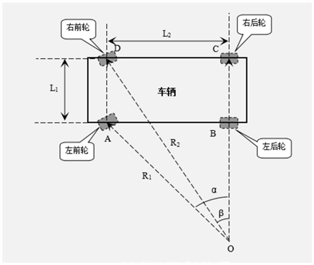
[0038] Such as figure 1 The geometric model diagram of the vehicle turning left is shown above, and the meanings of the parameters in the diagram are as follows:

[0039] Point A is the center point of the left front wheel;

[0040] Point B is the center point of the left rear wheel;

[0041] Point C is the center point of the right rear wheel;

[0042] Point D is the center point of the right front wheel;

[0043] Point O is the turning center point;

[0044] α is the angle between the line segment OC and OA, that is, the steering angle of the left front wheel;

[0045] β is the angle between the line segment OC and OD, that is, the steering angle of the right front wheel;

[0046] L 1 is the distance between point A and point D, representing the wheelbase of the vehicle;

[0047] L 2 is the distance between point C and point D, indicating the wheelbase of the vehicle;

[0048] R 1 is the distance between point A and point O, and represents the turning radius of the...

Embodiment 2

[0093] The present invention also provides a vehicle turning radius calculation terminal device, including a memory, a processor, and a computer program stored in the memory and operable on the processor. When the processor executes the computer program, the present invention is realized. Steps in the above method embodiment of the first embodiment of the invention.

[0094] Further, as an executable solution, the vehicle turning radius calculation terminal device is a host device installed on the vehicle, usually ABS, ESC controller, etc., through which the terminal device is connected to the wheel speed sensors of each wheel through the wiring harness. Connect to collect the travel speed of each wheel.


PUM


Abstract

The invention relates to a vehicle turning radius calculation method, terminal equipment and a storage medium, and the method comprises the steps: collecting the driving speed of each wheel in a vehicle driving process in real time through a wheel speed sensor in a vehicle; judging a turning direction according to a turning principle that the outer side wheel speed is greater than the inner side wheel speed; according to the driving speed of the left front wheel and the driving speed of the right front wheel, calculating the driving arc length of the left front wheel and the driving arc lengthof the right front wheel in single sampling time, and solving a binary equation set through a trigonometric function and a geometric position relation to obtain a left front wheel steering angle anda right front wheel steering angle; removing ambiguity values from the acquired multiple groups of data, averaging to obtain a final reliable left front wheel steering angle and a final reliable rightfront wheel steering angle, and finally calculating to obtain a left front wheel turning radius and a right front wheel turning radius. The method is simple to implement, high in accuracy, prospective, high in real-time performance, high in practicability, stable and reliable, does not need additional accessories, and has good application value and economic benefits.

Description

technical field [0001] The invention relates to the technical field of vehicles, in particular to a method for calculating the turning radius of a vehicle, a terminal device and a storage medium. Background technique [0002] The traditional method of calculating the turning radius of a vehicle is: install a steering wheel angle sensor on the steering wheel of the vehicle, collect the steering wheel angle signal in real time, calculate the inner and outer wheel angles according to the calibrated steering ratio factor of the inner and outer wheels of the car, and finally calculate the turning angle of the vehicle. radius. [0003] The traditional vehicle turning radius calculation technology uses hardware sensors, which require precise calibration of the sensors. It has many disadvantages: First, it uses an additional steering wheel angle sensor, which has a complex structure and is easily damaged, which increases the cost of the vehicle; The steering wheel angle collected b...

Claims


Application Information

Patent Timeline
Patent Type & Authority Applications(China)
IPC IPC(8): B60W40/10
CPCB60W40/10B60W2520/06B60W2520/28
Inventor 叶德焰朱进阳陈从华任赋
Owner 明见(厦门)技术有限公司
Learn More