
Three-dimensional pipeline stacking device

A three-dimensional, stacking technology, applied in the pipeline field, can solve the problems of inconvenient unloading, lack of lifting, and complicated operation, etc., and achieve the effects of reducing the risk of pipeline corrosion, improving space utilization, and increasing stacking capacity

Active Publication Date: 2021-02-26
ZHEJIANG ZHONGGONG PETROCHEMICAL EQUIP CO LTD
View PDF4 Cites 0 Cited by
  • Summary
  • Abstract
  • Description
  • Claims
  • Application Information

AI Technical Summary

Problems solved by technology

[0002] The existing pipe stacking rack has the advantages of high strength and simple appearance. In the past, pipes were basically stacked on the ground without a fixed pipe stacking device. Such a stacking method is easy to corrode the pipes and has a great impact on the pipes. It is large, and when stacked in the factory building, it takes up a lot of factory space, and the existing pipe stacking rack does not have the function of lifting. When stacking the pipes above the stacking rack, the operation is complicated and dangerous, and the The pipeline at the place is inconvenient for feeding

Method used


Image

  • Three-dimensional pipeline stacking device
  • Three-dimensional pipeline stacking device
  • Three-dimensional pipeline stacking device

Examples


Embodiment

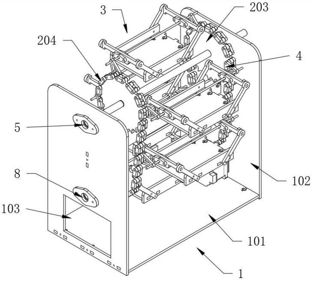
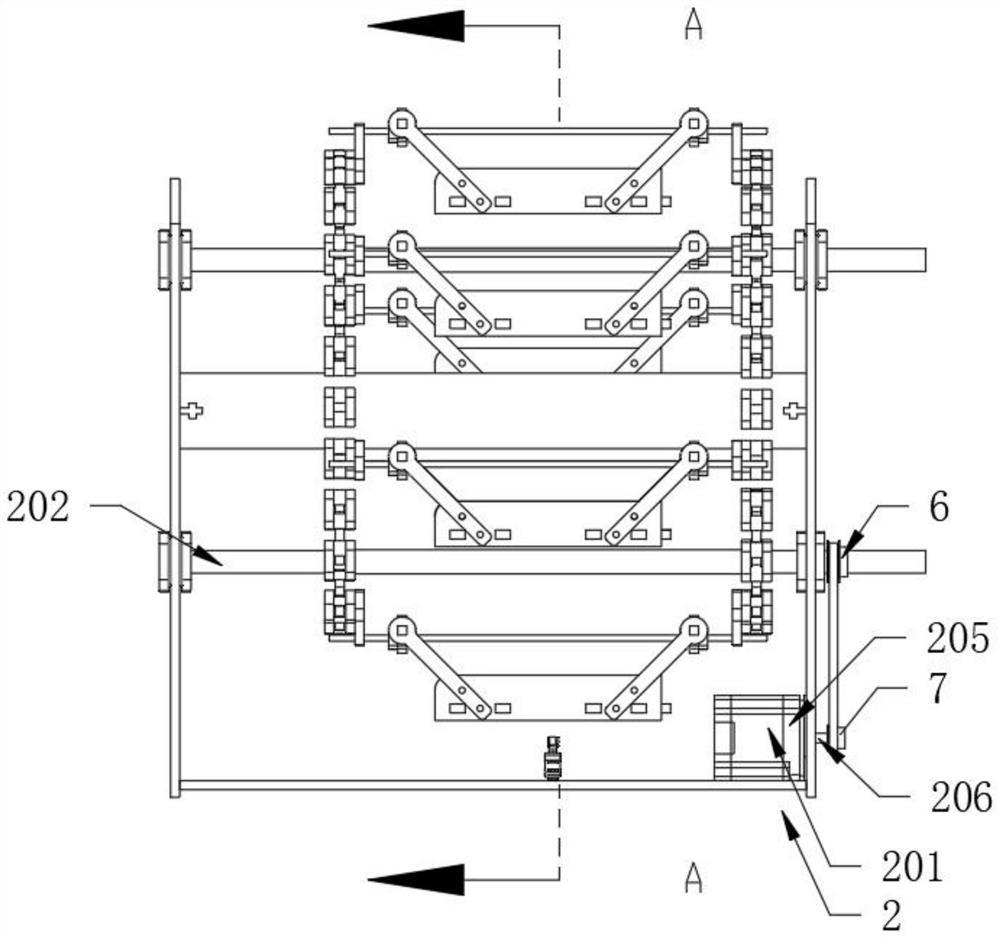
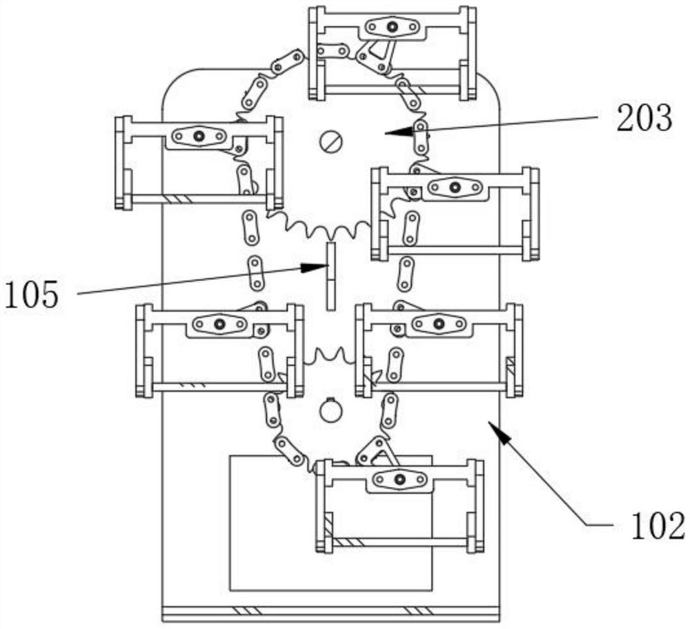
[0032] see Figure 1-8, the present invention provides the following technical solutions: a three-dimensional pipeline stacking device, comprising: a support structure 1, a drive mechanism 2 and a stacker 3 components.

[0033] Wherein the support structure 1 includes a support base 101, two sets of support risers 102 are fixedly connected to both sides of the support base 101, and a feed port 103 is opened below one of the support risers 102, and installation grooves are arranged on the two sets of support risers 102 104 , a support horizontal plate 105 is fixedly connected between two sets of support vertical plates 102 .

[0034] In this embodiment, the support structure 1 is used to support the entire device. The support base 101 is fixed on the ground of the factory building and fastened by expansion screws. Two sets of support risers 102 are fixed on both sides of the support base 101. Plate 102 is provided with installation groove 104, and installation groove 104 is pr...


PUM


Abstract

The invention provides a three-dimensional pipeline stacking device. The three-dimensional pipeline stacking device comprises a supporting structure, a driving mechanism and a stacking frame, whereinthe supporting structure comprises a supporting base, two groups of vertical supporting plates are fixedly connected to the two sides of the supporting base, a material port is formed below one vertical supporting plate, installation grooves are formed in the two groups of vertical supporting plates separately, and a transverse supporting plate is fixedly connected between the two groups of vertical supporting plates; the driving mechanism comprises a fixed driving motor installed at one side above the supporting base, two driving shafts arranged between the two groups of vertical supporting plates, driving discs arranged at the two ends of the driving shafts and a driving chain used for driving the upper driving disc and the lower driving disc to rotate; the stacking frame comprises a supporting frame, supporting rods fixedly installed at the two sides of the supporting frame, supporting connecting rods fixedly connected with the supporting rods and guide columns which penetrate through the supporting connecting rods and are fixedly connected with the supporting connecting rods, the stacking frame is arranged in a lifting mode, stacked pipelines can be conveniently lifted, and theheights of the stacked pipelines can be conveniently adjusted, so that loading and unloading for the pipelines are greatly facilitated.

Description

technical field [0001] The invention belongs to the technical field of pipelines, and in particular relates to a three-dimensional pipeline stacking device. Background technique [0002] The existing pipe stacking rack has the advantages of high strength and simple appearance. In the past, pipes were basically stacked on the ground without a fixed pipe stacking device. Such a stacking method is easy to corrode the pipes and has a great impact on the pipes. It is large, and when stacked in the factory building, it takes up a lot of factory space, and the existing pipe stacking rack does not have the function of lifting. When stacking the pipes above the stacking rack, the operation is complicated and dangerous, and the The pipeline at the place is inconvenient for cutting. Contents of the invention [0003] The object of the present invention is to provide a kind of three-dimensional pipe stacking device, aims to solve the problems mentioned in the above-mentioned backgrou...

Claims


Application Information

Patent Timeline
Patent Type & Authority Applications(China)
IPC IPC(8): B65G1/04
CPCB65G1/0471B65G2201/0276
Inventor 祝晓东杨志伟王晓李岩方红卫郑亚生俞晨曦胡志刚
Owner ZHEJIANG ZHONGGONG PETROCHEMICAL EQUIP CO LTD
Learn More