Roller brush for printing and dyeing
A technology of roller brushes and gears, applied in printing, printing machines, rotary printing machines, etc., can solve the problems of complicated operation, inability to adjust the length, and inconvenient work
- Summary
- Abstract
- Description
- Claims
- Application Information
AI Technical Summary
Problems solved by technology
Method used
Image
Examples
Embodiment 1
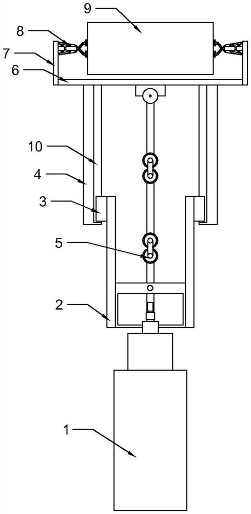
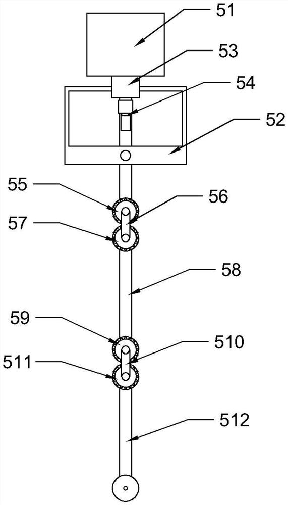
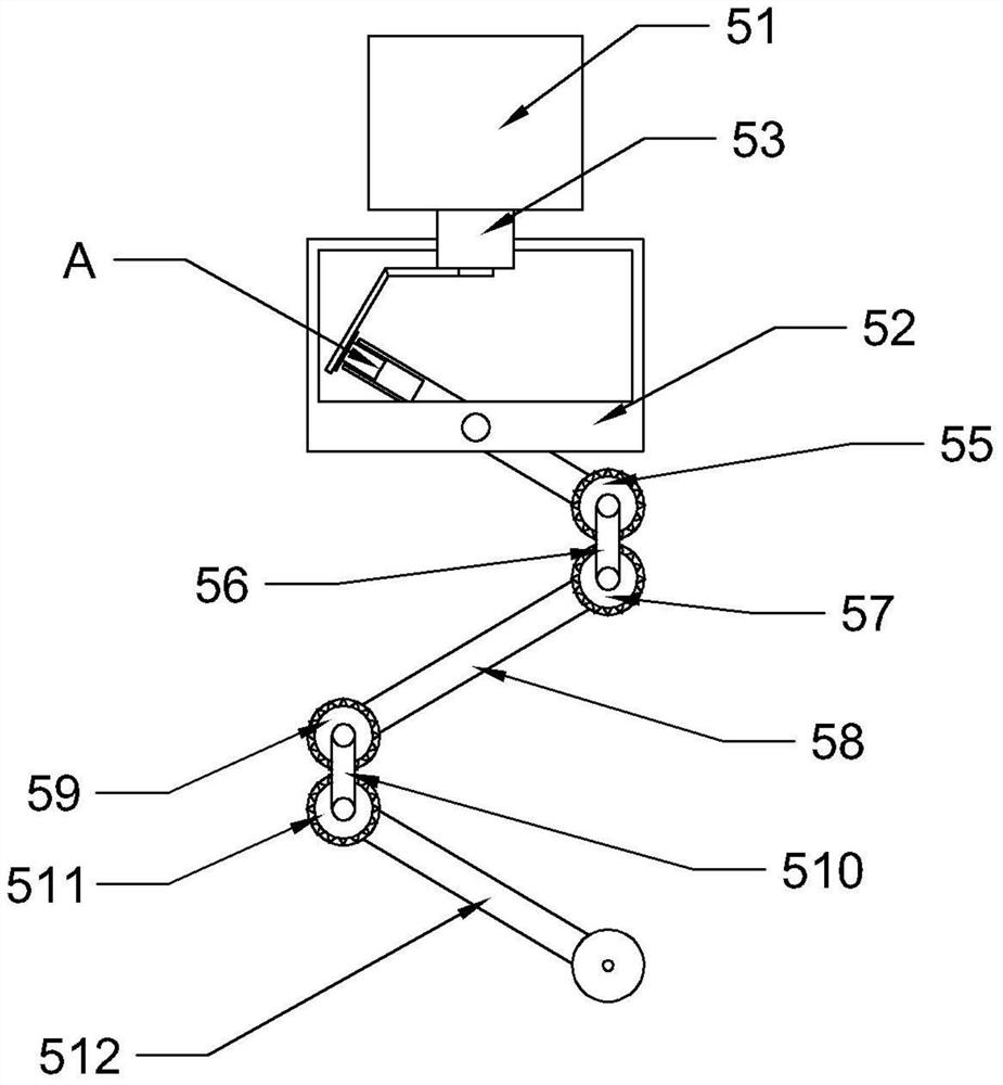
[0028] like Figure 2 to Figure 5 As shown, in the embodiment of the present invention, the telescopic device includes a console 54, a frame 52 is installed at the bottom of the console 51, a rotating motor 53 is installed above the inner wall of the frame 52, and a rotating motor 53 is installed below the rotating motor 53. A rotating device 54; a first gear 55 is fixedly installed below the rotating device 54, a first connecting rod 56 is hinged on the first gear 55, and a second gear 57 is hinged at the other end of the first connecting rod 56, so The first gear 55 meshes with the second gear 57, the second gear 57 is fixedly mounted with a second connecting rod 58, the other end of the second connecting rod 58 is fixedly mounted with a third gear 59, the third The gear 59 is hinged with a second connecting rod 510, the other end of the second connecting rod 510 is hinged with a fourth gear 511, the third gear 59 is meshed with the fourth gear 511, and the fourth gear 511 i...
Embodiment 2
[0032] like Figure 5 As shown, in the embodiment of the present invention, the rotating device 54 includes a first rotating rod 541, one end of the first rotating rod 541 is fixedly installed with the rotating motor 53, and the other end of the first rotating rod 541 is obliquely installed with a second Two rotating rods 542, the bottom of the other end of the second rotating rod 542 is equipped with a limiting rod 543; the bottom of the frame 52 is hinged with a first connecting rod 544, and one end of the first connecting rod 544 is equipped with a fan-shaped limiting piece 545, The limiting rod 543 is located between the fan-shaped limiting pieces 545 .
[0033]When in use, the rotating motor 53 will drive the first rotating rod 541 and the second rotating rod 542 to rotate, and then drive the limit rod 543 fixedly installed with the second rotating rod 542 to rotate. 545, so the limit rod 543 will move between the sector limit pieces 545, and at the same time, the sector...
Embodiment 3
[0035] Such as Figure 6 to Figure 8 As shown, in the embodiment of the present invention, the buffer clamping mechanism 8 includes a fixed rod 81, the side wall of the fixed rod 81 is symmetrically hinged with a first connecting rod 82, and the other end of the first connecting rod 82 is hinged with a second Two connecting rods 83, the other end of the second connecting rod 83 is hinged with a slide bar 84, one end of the slide bar 84 is provided with a groove 85, and the side wall of the other end of the slide bar 84 is symmetrically mounted with a fixed pulley 86. The other end of the slide bar 84 is symmetrically hinged with a third connecting rod 87, and the other end of the third connecting rod 87 is hinged with a splint 88; one end of the fixed rod 81 is fixedly equipped with a telescopic rod 89, and the other end of the telescopic rod 89 is fixedly connected There is a first spring 810, and the other end of the first spring 810 is fixedly connected to the bottom of the...
PUM
 Abstract
Description
Claims
Application Information
 - R&D
- Intellectual Property
- Life Sciences
- Materials
- Tech Scout
- Unparalleled Data Quality
- Higher Quality Content
- 60% Fewer Hallucinations
Browse by: Latest US Patents, China's latest patents, Technical Efficacy Thesaurus, Application Domain, Technology Topic, Popular Technical Reports.
© 2025 PatSnap. All rights reserved.Legal|Privacy policy|Modern Slavery Act Transparency Statement|Sitemap|About US| Contact US: help@patsnap.com


