Arc infolding rotating mechanism with invariable tangent point
A technology of rotating mechanism and arc, applied to the field of inner folding connecting shaft and arc inner folding rotating mechanism, can solve the problems of a large number of spare parts and inconvenient industrialized manufacturing, and achieve the effect of simple and effective structural design and easy industrialization implementation.
- Summary
- Abstract
- Description
- Claims
- Application Information
AI Technical Summary
Problems solved by technology
Method used
Image

Examples
Embodiment 1
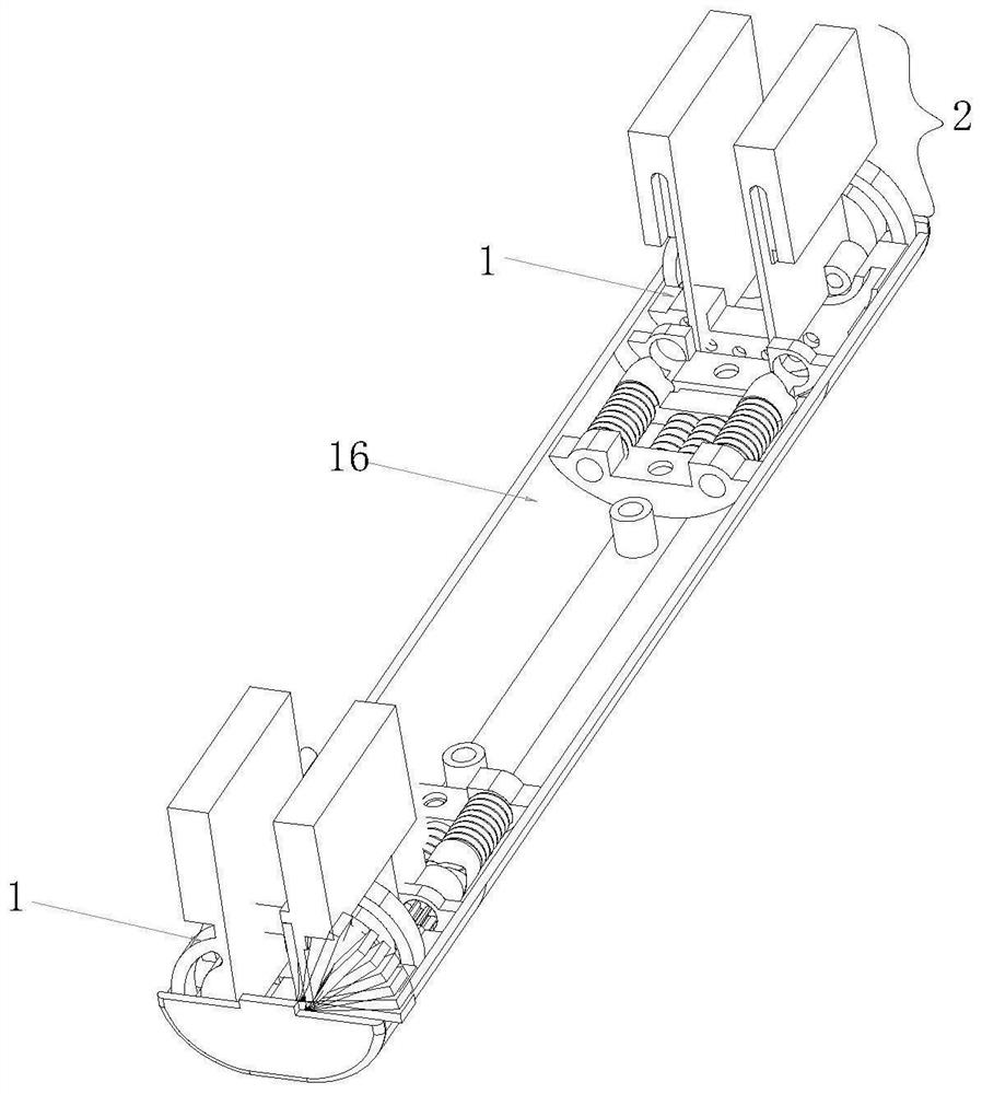
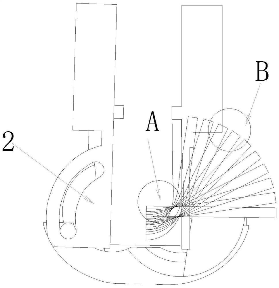
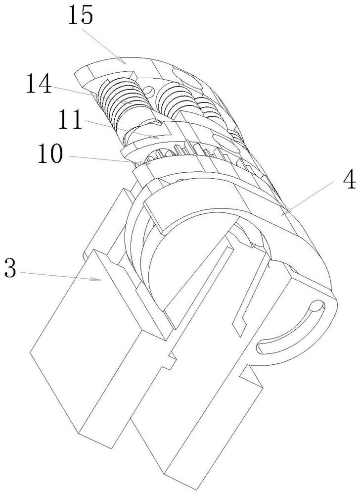
[0049] Such as Figure 9-14 As shown, the arc inward turning mechanism with no tangent point disclosed in this embodiment includes a rotating shaft 1, and the rotating shaft 1 includes a rotating mechanism 2, and the rotating mechanism 2 includes two sets of turrets 3 distributed laterally. Between the said turret 3, there are longitudinally distributed and rotatably connected circular arc groove movable blocks 4 and two groups of circular arc sliders 5. Slidingly connected arc chute 41, the arc slider 5 reciprocatingly slides in the arc chute 41 to realize U-shaped inward bending rotation with constant tangent point of 0°-180° motion track;
[0050] Between described turret 3 and described arc groove movable block 4, realize rotation through the sliding cooperation of sliding column 6 and curved groove 7; A rotating column 51 is provided, and the rotating connection between the rotating frame 3 and the arc slider 5 is realized through the rotating cooperation between the rot...
Embodiment 2
[0052] Such as Figure 15-20 As shown, the arc inward turning mechanism with no tangent point disclosed in this embodiment includes a rotating shaft 1, and the rotating shaft 1 includes a rotating mechanism 2, and the rotating mechanism 2 includes two sets of turrets 3 distributed laterally. Between the said turret 3, there are longitudinally distributed and rotatably connected circular arc groove movable blocks 4 and two groups of circular arc sliders 5. Slidingly connected arc chute 41, the arc slider 5 reciprocatingly slides in the arc chute 41 to realize U-shaped inward bending rotation with constant tangent point of 0°-180° motion track;
[0053]Between described turret 3 and described arc groove movable block 4, realize rotation through the sliding cooperation of sliding column 6 and curved groove 7; A rotating column 51 is provided, and the rotating connection between the rotating frame 3 and the arc slider 5 is realized through the rotating cooperation between the rot...
Embodiment 3
[0055] Such as Figure 20-26 As shown, the arc inward turning mechanism with no tangent point disclosed in this embodiment includes a rotating shaft 1, and the rotating shaft 1 includes a rotating mechanism 2, and the rotating mechanism 2 includes two sets of turrets 3 distributed laterally. Between the said turret 3, there are longitudinally distributed and rotatably connected circular arc groove movable blocks 4 and two groups of circular arc sliders 5. Slidingly connected arc chute 41, the arc slider 5 reciprocatingly slides in the arc chute 41 to realize U-shaped inward bending rotation with constant tangent point of 0°-180° motion track;
[0056] Between described turret 3 and described arc groove movable block 4, realize rotation through the sliding cooperation of sliding column 6 and curved groove 7; A rotating column 51 is provided, and the rotating connection between the rotating frame 3 and the arc slider 5 is realized through the rotating cooperation between the ro...
PUM
 Abstract
Description
Claims
Application Information