Eureka AIR delivers breakthrough ideas for toughest innovation challenges, trusted by R&D personnel around the world.

Under-bed countercurrent ignition device of circulating fluidized bed boiler

A technology of circulating fluidized bed and ignition device, which is applied in the direction of fluidized bed combustion equipment, combustion ignition, and molten fuel burning, etc., can solve the problems of long air duct design, huge equipment weight, and increased boiler ignition fuel consumption.

Pending Publication Date: 2021-02-26
胡建廷
View PDF0 Cites 0 Cited by
  • Summary
  • Abstract
  • Description
  • Claims
  • Application Information

AI Technical Summary

Problems solved by technology

[0002] At present, the under-bed air duct ignition devices widely used in thermal power generation circulating fluidized bed boilers have the common feature that the air duct shell is welded with metal steel plates, and the air duct lining is made of high-temperature refractory materials. Due to the excessive weight, the entire air duct is made of heavy-duty The steel hanger support, based on the unilateral consideration of the boiler factory technicians, allows the hot and cold air to be fully mixed, and the entire air duct is designed to be relatively long. Construction and maintenance, as well as boiler ignition fuel consumption in the operating costs have all increased significantly. For this reason, technical optimization must be carried out

Method used


Image

  • Under-bed countercurrent ignition device of circulating fluidized bed boiler
  • Under-bed countercurrent ignition device of circulating fluidized bed boiler

Examples


Embodiment Construction

[0006] The present invention is described in further detail below with reference to accompanying drawing:

[0007] Structural description of the present invention is as follows:

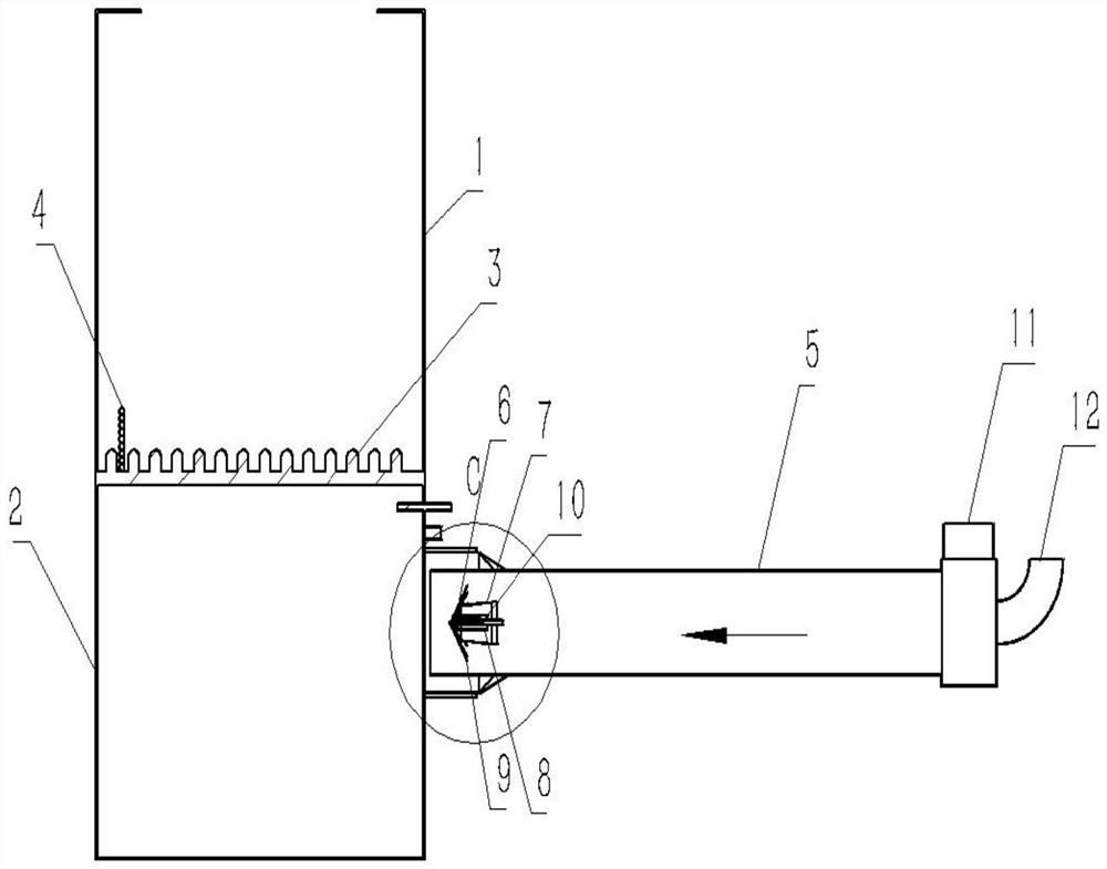
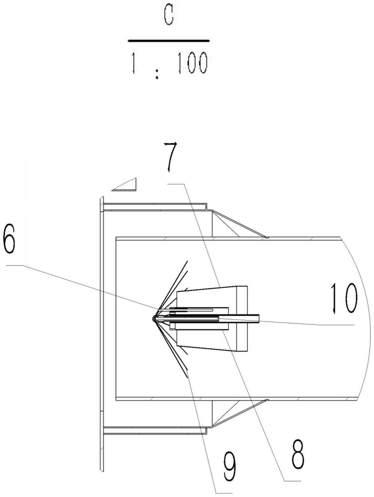
[0008] Refer to attached figure 1 , attached figure 2 As shown, the countercurrent ignition device under the circulating fluidized bed boiler mainly includes: a boiler, an ignition air duct and a countercurrent oil gun combined burner; the boiler mainly includes: a furnace 1, an air chamber 2, a fluidized bed body 3, Bed material 4; the ignition air duct includes: main air duct 5, square and round joints 13, combustion air inlets 11, 12; Fuel-saving and environment-friendly oil gun 10, ignition gun 6, flame stabilizer-oil gun conduit-inner air cylinder assembly 8 and flame jet 9.

[0009] Wherein the circulating fluidized bed boiler bed countercurrent ignition device includes: a boiler, the boiler mainly includes a furnace 1, an air chamber 2 and a fluidized bed bed body 3; the bed material 4 is ...


PUM


Abstract

The invention relates to a boiler combustion device, in particular to an under-bed countercurrent ignition device of a circulating fluidized bed boiler, which is widely used in the process of ignitingand starting the circulating fluidized bed boiler of a power station. The under-bed countercurrent ignition device mainly comprises a boiler, an ignition air duct and a countercurrent oil gun combined combustor, wherein the countercurrent oil gun combined combustor comprises a reducing air duct, a supersonic speed oil-saving environment-friendly oil gun, an ignition gun, a flame holder-oil gun guide pipe-inner air duct assembly and flame jet. The under-bed countercurrent ignition device is technically characterized in that the flame jet of the supersonic speed oil-saving environment-friendlyoil gun is jetted towards the incoming flow direction of combustion-supporting air and is in contact with cold air in advance, the combustion is violent, the length and the size of flame can be reduced, and the technical guarantee is provided for under-bed ignition of the boiler.

Description

technical field [0001] The invention relates to a boiler combustion device, in particular to a countercurrent ignition device under the bed of a circulating fluidized bed boiler widely used in the ignition and start-up process of various levels and types of circulating fluidized bed power station boilers. Background technique [0002] At present, the under-bed air duct ignition devices widely used in thermal power generation circulating fluidized bed boilers have the common feature that the air duct casing is welded with metal steel plates, and the air duct lining is made of high-temperature refractory materials. Due to the excessive weight, the entire air duct is made of heavy-duty The steel hanger support is based on the unilateral consideration of the boiler factory technicians, so that the hot and cold air can be fully mixed, and the entire air duct is designed to be relatively long. The construction and maintenance of the boiler, as well as the fuel consumption of boile...

Claims


Application Information

Patent Timeline
Patent Type & Authority Applications(China)
IPC IPC(8): F23C10/18F23Q13/00
CPCF23C10/18F23C2206/10F23Q13/00
Inventor 胡建廷
Owner 胡建廷
Why Eureka
Eureka Blog
Learn More