
Hand warmer for office work

A heater and hand technology, applied in the application, home heating, home appliances and other directions, can solve the problems of inconvenient hand warmth, inconvenient use, fast heat dissipation, etc., to avoid rapid dissipation, easy to use, and not easy to wear out.

Inactive Publication Date: 2021-02-26
万发之
View PDF0 Cites 0 Cited by
  • Summary
  • Abstract
  • Description
  • Claims
  • Application Information

AI Technical Summary

Problems solved by technology

[0003] The object of the present invention is to provide a hand warmer for office use, to solve the problems of fast heat dissipation and high energy consumption in the existing heating device proposed in the background technology, and it is inconvenient to keep the hands warm during office work, and it is not convenient. Ease of use

Method used


Image

  • Hand warmer for office work
  • Hand warmer for office work
  • Hand warmer for office work

Examples


Embodiment 1

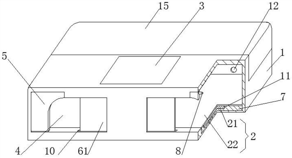
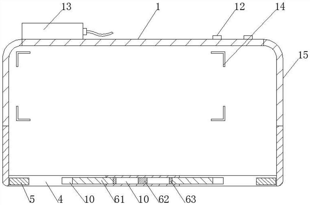
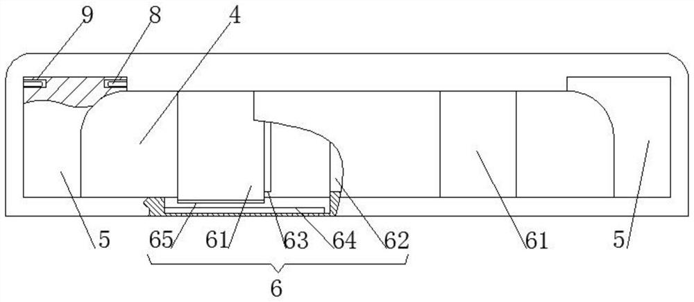
[0029] see Figure 1-4 , this embodiment provides a hand warmer for office use, including a housing 1, a heating device 2 is fixedly installed on the bottom of the housing 1, a silica gel plate 3 is fixedly connected to the upper side of the housing 1, and a Opening 4, both sides of opening 4 are rotatably connected with heat preservation board 5, a moving device 6 is arranged between the two heat preservation boards 5, a wire hole 12 is opened on one side of the shell 1, and a protective shell 13 is fixedly connected to one side of the shell 1 Preferably, the side away from the opening 4 above the casing 1 is tempered glass 15, which is convenient for watching the mouse and keyboard, and is convenient for office operation; preferably, a temperature controller, a temperature sensor and a relay are installed in the protective case 13 of the device, and the temperature sensor and The interface on one side of the relay is connected to the temperature controller, and the interface...

Embodiment 2

[0040] see Figure 1-4 , On the basis of Embodiment 1, a further improvement has been made: a groove body 11 for installing a heating plate 21 is opened above the heat insulating plate 7 .

[0041] Wherein, the tank body 11 facilitates the installation of the heating plate 21 .

[0042] In the embodiment, both the wire hole 12 and the protective shell 13 are located on the side of the shell 1 away from the opening 4 .

[0043] Wherein, the wire hole 12 and the protective shell 13 are located on the side of the shell 1 away from the opening 4, so as to facilitate the connection of the mouse and keyboard wires to the computer host.

[0044] In the embodiment, a stopper 14 is fixedly connected to the bottom of the cavity of the housing 1 .

[0045] Wherein, the block 14 is convenient for placing the keyboard and prevents the keyboard from moving.

[0046] A kind of office hand warmer according to claim 1, its use method is:

[0047] S1. Put the mouse and keyboard into the inn...


PUM


Abstract

The invention discloses a hand warmer for office work. The hand warmer comprises a shell, wherein a heating device is fixedly arranged at the bottom of the shell; a silica gel plate is fixedly connected to one side of the upper part of the shell; an opening is arranged in one side of the shell; insulation boards are rotationally connected to the two sides of the opening; a moving device is arranged between the two insulation boards; the heating device comprises a heating plate and a heat conduction plate; the heating plate is fixedly arranged at the bottom of the shell through a heat insulating plate; the heat conduction plate is fixedly arranged above the heat insulating plate; fixing shafts used for being rotationally connected to the insulation boards are fixedly arranged on the side walls of the two sides of the opening; and limiting holes used for being connected to the corresponding fixing shaft are arranged in the two sides of each insulation board. The shell, the heating deviceand the moving device are designed as main structures of the hand warmer for office work, through internal warm-keeping measures, the heat is not prone to loss, the energy consumption is greatly reduced, and the energy can be effectively saved.

Description

technical field [0001] The invention relates to the field of heating equipment, in particular to a hand warmer for office use. Background technique [0002] A heater refers to equipment used for heating. There are many types of heaters. The most common electric heater is a heating device that uses electricity as energy for heating and heating. It can also be called electric heating. The existing heaters include heaters, small The sun and the like are used to heat the heat source to the outside. This kind of device has the problems of fast heat dissipation and high energy consumption, and it is not convenient to keep the hands warm when working, and it is not convenient to use. In order to solve the above problems, it is proposed A hand warmer for office use. Contents of the invention [0003] The object of the present invention is to provide a hand warmer for office use, to solve the problems of fast heat dissipation and high energy consumption in the existing heating dev...

Claims


Application Information

Patent Timeline
IPC IPC(8): F24D13/02F24D19/00
CPCF24D13/02F24D19/00
Inventor 万发之
Owner 万发之
Learn More