Shell for filling gelatinized solid-liquid phase mixed fuel with stirring function

A mixed fuel, solid-liquid phase technology, used in nuclear power generation, ammunition testing, greenhouse gas reduction, etc.

Active Publication Date: 2021-02-26
XIAN MODERN CHEM RES INST
View PDF8 Cites 7 Cited by
  • Summary
  • Abstract
  • Description
  • Claims
  • Application Information

AI Technical Summary

Problems solved by technology

During the process of filling fuel into the warhead casing, the gelled solid-liquid phase mixed fuel flows from the outside to the inside, and the air in the warhead casing is discharged from the inside to the outside, and the air and the gelled solid-liquid phase mixed fuel generate Due to the convective movement, the air will inevitably enter the gelled solid-liquid mixed fuel. Due to the high viscosity of the fuel, after the air enters the fuel, it will be suspend...

Method used


Image

  • Shell for filling gelatinized solid-liquid phase mixed fuel with stirring function

Examples


Embodiment 1

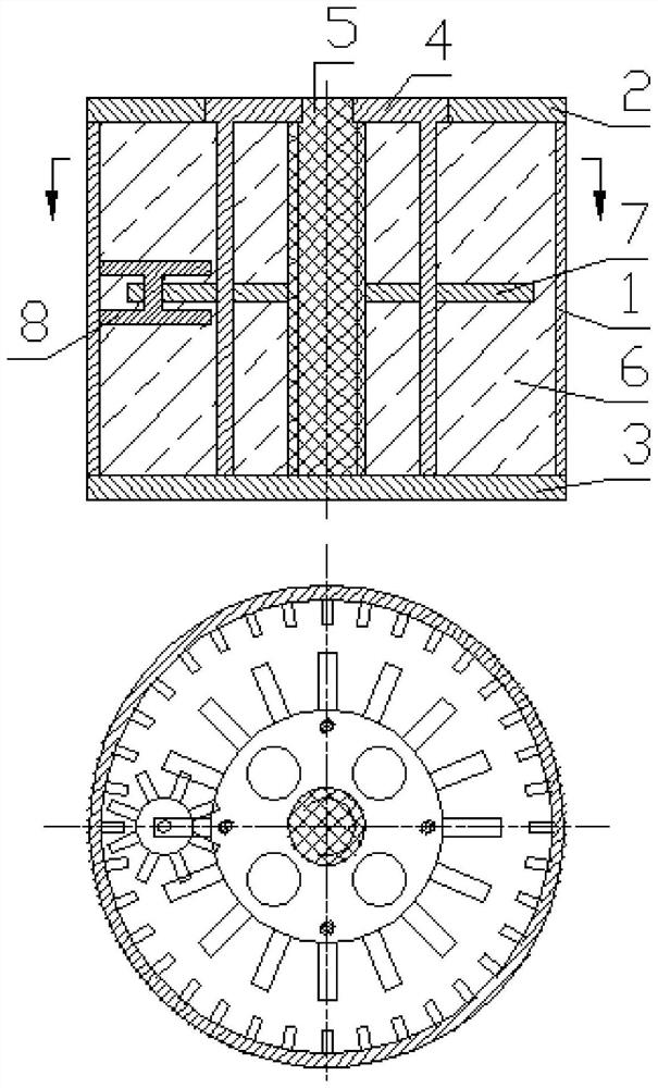
[0059] Such as figure 1 As shown, this embodiment provides a gelled solid-liquid phase mixed fuel shell with a stirring function, including an upper end cover 2 , a lower end cover 3 , and a gelled solid-liquid phase mixed fuel 6 . It is characterized in that it also includes a housing 1, a support frame 4, a throwing device 5, an axially moving stirring plate 7, and a circularly moving stirring plate 8;

[0060] The housing 1 is a first cylindrical body, the first cylindrical body of the housing 1 is a rotating body, the upper end surface of the first cylindrical body of the housing 1 is the first upper concentric annular surface, and the first circular surface of the housing 1 The lower end surface of the cylinder body is the first lower end concentric annular surface, the inner side surface of the first cylinder of the housing 1 is the first inner cylindrical surface, and thirty-six first vertical cylinders are connected to the first inner cylindrical surface of the housing...

Embodiment 2

[0104] Such as figure 1 As shown, this embodiment provides a gelled solid-liquid phase mixed fuel shell with a stirring function, including an upper end cover 2 , a lower end cover 3 , and a gelled solid-liquid phase mixed fuel 6 . It is characterized in that it also includes a housing 1, a support frame 4, a throwing device 5, an axially moving stirring plate 7, and a circularly moving stirring plate 8;

[0105] The housing 1 is a first cylindrical body, the first cylindrical body of the housing 1 is a rotating body, the upper end surface of the first cylindrical body of the housing 1 is the first upper concentric annular surface, and the first circular surface of the housing 1 The lower end surface of the cylinder body is the first lower end concentric annular surface, the inner side surface of the first cylinder of the housing 1 is the first inner cylindrical surface, and thirty-six first vertical cylinders are connected to the first inner cylindrical surface of the housing...


PUM

PropertyMeasurementUnit
Thicknessaaaaaaaaaa
Thicknessaaaaaaaaaa

Abstract

The invention discloses a shell for filling gelatinized solid-liquid phase mixed fuel with a stirring function. The shell is characterized in that the lower end of an eighth outer cylindrical surfaceof an annular motion stirring disc is provided with eight eighth lower end cylindrical bosses which are uniformly distributed in the circumferential direction, the axis of each eighth lower end cylindrical boss of the annular motion stirring disc is vertical to the axis of a revolving body of the annular motion stirring disc, an eighth annular groove is formed in the middle of an eighth outer cylindrical surface of the annular motion stirring disc, and the inner side surface of the eighth annular groove of the annular motion stirring disc is an eighth middle outer cylindrical surface. The warhead shell has the function of stirring internal fuel, and solid-phase fuel, liquid-phase fuel and gel are stirred in the warhead shell until the solid-phase fuel, the liquid-phase fuel and the gel areuniformly mixed; air is prevented from being in contact with the gelatinized solid-liquid phase mixed fuel, no air exists in the fuel finally, and the power design of the warhead is met; and the riskof combustion is avoided, and the safety of the warhead is ensured.

Description

technical field [0001] The invention belongs to the technical field of filling fuel casings, and relates to a casing for filling a gelled solid-liquid phase mixed fuel, in particular to a gelled solid-liquid phase mixed fuel casing with a stirring function. Background technique [0002] The body detonation warhead is filled with high-energy liquid-phase fuel, driven by the explosion and throwing of explosives, the high-energy liquid-phase fuel is thrown into the air, and the high-energy liquid-phase fuel is atomized and mixed with air to form a large-scale active cloud. The explosive is detonated twice, and the active cloud group produces a body detonation, which releases a strong shock wave. The power of the shock wave exceeds the explosion power of multiple times the mass of TNT. It is one of the most powerful non-nuclear weapons. [0003] The improvement of the explosive power of the body detonation warhead mainly depends on the improvement of the energy of the internally...

Claims


Application Information

Patent Timeline
IPC IPC(8): F42B33/02F42B35/00C06B21/00
CPCF42B33/02F42B35/00C06B21/00C06B21/0008Y02E30/30
Inventor 许志峰柳雯赵超越袁宝慧郭双锋
Owner XIAN MODERN CHEM RES INST
Why Eureka
Try Eureka