Crankshaft blank center hole run-out testing fixture

A center hole and crankshaft technology, applied in the field of crankshaft blank center hole runout inspection tool, can solve the problems of time-consuming, inability to achieve 100% inspection, low inspection efficiency, etc., to improve inspection efficiency, reduce workpiece handling and assembly and disassembly, and reduce inspection. effect of time

Active Publication Date: 2021-02-26
桂林福达重工锻造有限公司
View PDF19 Cites 0 Cited by
  • Summary
  • Abstract
  • Description
  • Claims
  • Application Information

AI Technical Summary

Problems solved by technology

The traditional center hole runout detection method is to put the crankshaft blank after machining the center hole on the deflection meter and use the dial indicator for detection. It takes a long time to use the deflection meter

Method used


Image

  • Crankshaft blank center hole run-out testing fixture
  • Crankshaft blank center hole run-out testing fixture
  • Crankshaft blank center hole run-out testing fixture

Examples


Embodiment 1

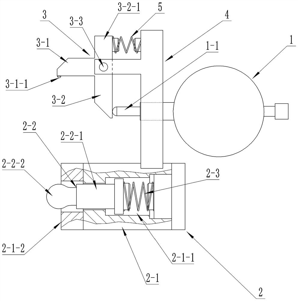
[0028] see figure 1 , a crankshaft blank central hole runout test tool, including a dial indicator 1, also includes a reference seat 2, a measuring swing arm 3, a connecting frame 4,

[0029] The reference seat includes a seat body 2-1, a positioning head 2-2, and a first compression spring 2-3. A cavity 2-1-1 is provided inside the seat body, and a vertical positioning plane 2-1 is provided on the left side of the seat body. 1-2, the middle part of the positioning plane 2-1-2 is provided with a through hole communicating with the cavity 2-1-1, the positioning head 2-2 includes a guide rod 2-2-1 and a spherical head 2-2-2, the guide The rod 2-2-1 is arranged horizontally, and the spherical head 2-2-2 is fixedly connected to the center of the left end surface of the guide rod 2-2-1. In this embodiment, the first compression spring 2-3 is horizontally installed in the cavity of the seat body In 2-1-1, the left and right ends of the first compression spring 2-3 are respectively ...

Embodiment 2

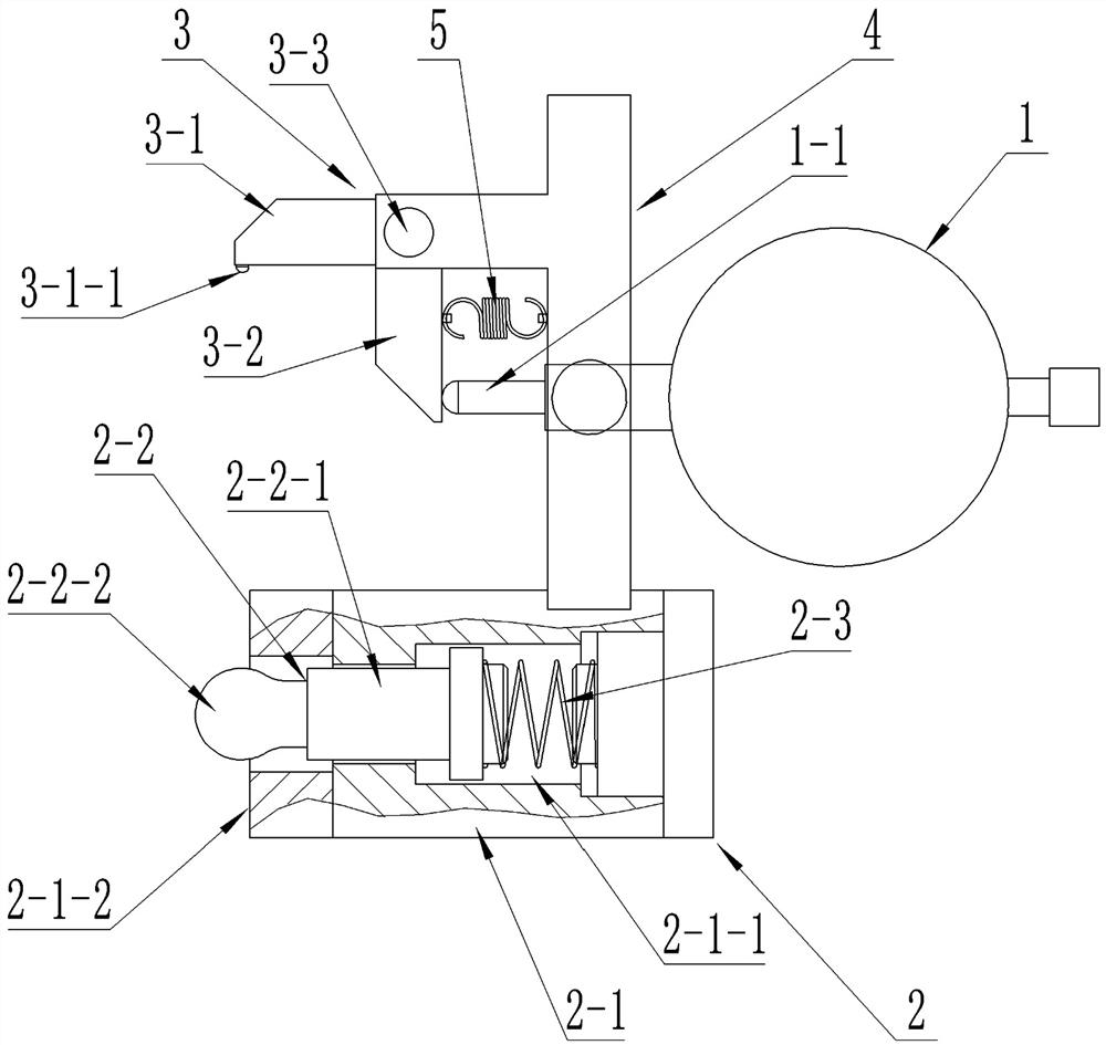
[0035] see image 3 The difference between this embodiment and the first embodiment is that the protrusion on the upper part of the vertical swing rod is canceled, the second elastic member 5 is a tension spring, and the tension spring is installed at the bottom of the vertical swing rod, and the left and right sides of the tension spring The two ends are respectively connected to the vertical swing rod 3-2 and the connecting frame 4, and the tension of the tension spring makes the measuring swing arm 3 have a tendency to rotate counterclockwise. Other structures and usage methods are the same as in the first embodiment.

Embodiment 3

[0037] see Figure 4 The difference between this embodiment and the second embodiment is that the second elastic member 5 is a torsion spring, and the torsion spring is installed on the rotating shaft 3-3. The restoring force of the torsion spring makes the measuring swing arm 3 produce a tendency to rotate counterclockwise. Other structures and The method of use is the same as in Example 1.


PUM


Abstract

The invention belongs to the field of crankshaft production detection, and particularly relates to a crankshaft blank center hole run-out testing fixture which comprises a dial indicator, a referenceseat, a measuring swing arm and a connecting frame, the reference seat comprises a seat body, a positioning head and a first elastic piece, the positioning head comprises a guide rod and a spherical ejector head, and the positioning head can only move left and right; the distances between a hard alloy measuring head of the measuring swing arm and the rotating shaft and between the meter rod contact and the rotating shaft are equal. The bottom of the connecting frame is fixedly connected with the seat body, the measuring swing arm is rotatably installed on the upper portion of the connecting frame through a rotating shaft of the measuring swing arm, and the measuring swing arm tends to rotate anticlockwise under the action of a second elastic piece. The dial indicator is arranged in middleof connecting frame, and an indicator rod head leftwards abuts against an indicator rod contact of a vertical swing rod. The testing fixture has the advantages that the operation is simple, the detection is fast and convenient, the 100 percent detection is favorably realized, the requirement on the placement position of a detected workpiece is low, the workpiece measurement is more flexible, and the labor intensity of workers is reduced.

Description

technical field [0001] The invention belongs to the field of crankshaft production detection, and in particular refers to a runout inspection tool for the central hole of a crankshaft blank. Background technique [0002] Crankshaft products require high precision for the center hole of the blank. Once the center hole jumps too much, it will lead to uneven machining allowance and difficult processing. In severe cases, the machining allowance will be insufficient and scrapped. Not scrapped. In order to ensure that the runout of the center hole of the crankshaft blank is within the technical requirements, it is necessary to inspect the runout of the center hole. The traditional center hole runout detection method is to put the crankshaft blank after machining the center hole on the deflection meter and use the dial indicator for detection. It takes a long time to use the deflection meter for inspection. It takes 5 minutes to measure one piece, and the detection efficiency is l...

Claims


Application Information

Patent Timeline
IPC IPC(8): G01B5/00
CPCG01B5/00
Inventor 周积信彭添陈清玲
Owner 桂林福达重工锻造有限公司
Why Eureka
Try Eureka