Drawer type pipeline sediment ground sampler and sampling method thereof
A sediment and sampler technology, which is applied to the drawer-type pipeline sediment well sampler and its sampling field, can solve the problems of potential safety hazards and cumbersome sediment sampling, so as to facilitate manual force application, avoid manual downhole sampling, and equipment The effect of great flexibility
- Summary
- Abstract
- Description
- Claims
- Application Information
AI Technical Summary
Problems solved by technology
Method used
Image

Examples
Embodiment 1
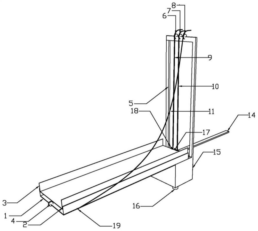
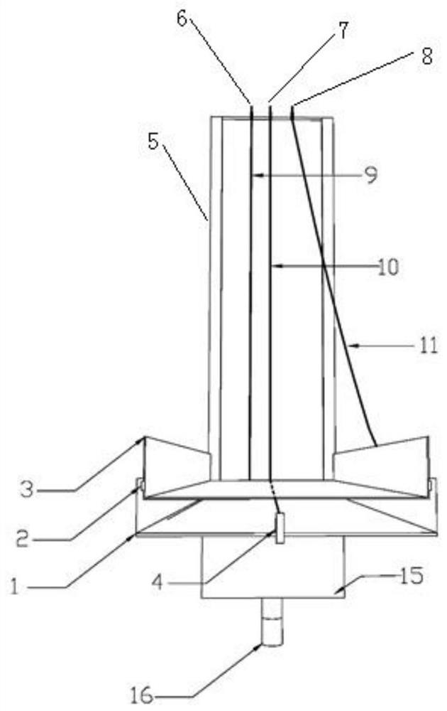
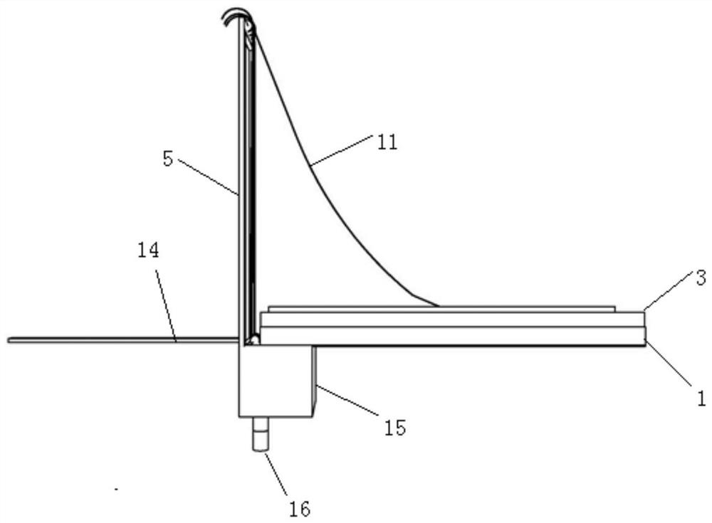
[0039] A drawer-type pipeline sediment well sampler, comprising a slide rail frame 1 positioned in the horizontal direction, a sediment sampling tank 3 slidably connected to the slide rail frame 1, a sediment sampling tank located at the bottom of the rear end of the slide rail frame 1 storage box 15, a first driving mechanism for driving the sediment sampling tank 3 to slide forward, a second driving mechanism for driving the sediment sampling tank 3 to slide backward, and a first driving mechanism for driving the sediment sampling tank 3 to tilt Three driving mechanisms;
[0040] Wherein: the rear end of the slide rail frame 1 is hinged with the top of the sediment storage tank 15, the sediment sampling tank 3 is open at both ends, the sediment storage tank 15 is open at the top, and the sediment storage tank 15 is open at the top. The top of 15 is fixed with the control frame 5 that is positioned at vertical direction;
[0041] The first drive mechanism includes a first fi...
Embodiment 2
[0051] As a preferred manner, the bottom of the sediment storage tank 15 is fixed with a support rod 16 . The support rod 16 can support the sediment sampling tank 3 to a certain height, so that it is aligned with the sediment in the pipeline.
[0052] As a preferred manner, the support rod 16 is a telescopic rod. Its length can be adjusted according to actual working conditions, and it is suitable for sediment sampling operations in different environments.
[0053] As a preferred manner, the rear portion of the sediment storage tank 15 is provided with an auxiliary support rod 14 hinged thereto. When in use, the auxiliary support rod 14 is adjusted to form a certain angle with the sediment storage tank 15, so that the device is stably supported at the bottom of the inspection well. In the non-working state, the auxiliary support rod 14 is attached to the control frame 5 .
[0054] As a preferred manner, the auxiliary support rod 14 is a telescopic rod. Its length can be a...
Embodiment 3
[0057] As a preferred mode, slide rails 2 are fixed on the inside of the two side walls of the slide rail frame 1, and slide bars are fixed on the outside of the two side walls of the sediment sampling tank 3, and the slide bars are connected to the The slide rail 2 is slidingly connected. The slide rail is a dovetail groove guide rail, and the structure of the slide bar is matched with the dovetail groove guide rail, and the slide rail is for the sediment sampling tank 3 to slide to play a guiding role.
[0058] As a preferred manner, the slide rail frame is a bar-shaped tank structure with a right-angled "U" shape in cross section, and the sediment sampling tank 3 is a bar-shaped tank structure with a right-angled "U" shape in cross-section. The width of the sediment sampling groove 3 is slightly smaller than the width of the slide rail frame 1 .
[0059] As a preferred manner, the bottom surface of the sediment sampling tank 3 is an arc surface structure. The bottom surfa...
PUM
 Abstract
Description
Claims
Application Information
 - R&D
- Intellectual Property
- Life Sciences
- Materials
- Tech Scout
- Unparalleled Data Quality
- Higher Quality Content
- 60% Fewer Hallucinations
Browse by: Latest US Patents, China's latest patents, Technical Efficacy Thesaurus, Application Domain, Technology Topic, Popular Technical Reports.
© 2025 PatSnap. All rights reserved.Legal|Privacy policy|Modern Slavery Act Transparency Statement|Sitemap|About US| Contact US: help@patsnap.com