Out-of-control prevention method and system for electric power tower inspection unmanned aerial vehicle

A technology for power towers and unmanned aerial vehicles is applied in the field of anti-runaway control methods and systems for power tower inspection unmanned aerial vehicles, which can solve the problems of large cumulative error, electromagnetic interference, and difficulty in adapting to the needs of unmanned aerial vehicles.

Pending Publication Date: 2021-02-26
STATE GRID ANHUI ELECTRIC POWER CO LTD HUAINAN POWER SUPPLY CO +3
10 Cites 1 Cited by

AI-Extracted Technical Summary

Problems solved by technology

UAVs using satellite, geomagnetic and other navigation methods are extremely susceptible to electromagnetic interference in some scenarios, especially power inspection UAVs, which will seriously interfere with UAV navigation systems, causing harm to UAVs, their surrounding environmen...

Method used

[0064] By fusing satellite navigation information and inertial navigation information, the anti-jamming ability of the inspection drone is significantly improved.
[0079] Through real-time monitoring of th...

Abstract

The invention discloses an out-of-control prevention method for an electric power tower inspection unmanned aerial vehicle. The out-of-control prevention method comprises the steps of S1 acquiring theGPS real-time position of the inspection unmanned aerial vehicle in the flight process; S2 calculating the position of the inspection unmanned aerial vehicle according to the flight acceleration measured by an unmanned aerial vehicle inertial navigation system; S3 judging whether the inspection unmanned aerial vehicle is subjected to external interference or not by utilizing the GPS real-time position obtained in the step S1 and the unmanned aerial vehicle position obtained in the step S2; and S4 starting a GPS mode to fly when the inspection unmanned aerial vehicle is not interfered, starting an inertial navigation mode to fly when the inspection unmanned aerial vehicle is interfered, and repeating the steps S1 to S3 in real time in the flight process until the flight is finished. The invention further discloses an out-of-control prevention system for the electric power tower inspection unmanned aerial vehicle and the unmanned aerial vehicle using the out-of-control prevention system. Through multi-source navigation information fusion, the precision and the anti-interference capability of the unmanned aerial vehicle navigation system can be improved.

Application Domain

Position/course control in three dimensions

Technology Topic

Automotive engineeringInertial navigation system +3

Image

  • Out-of-control prevention method and system for electric power tower inspection unmanned aerial vehicle
  • Out-of-control prevention method and system for electric power tower inspection unmanned aerial vehicle
  • Out-of-control prevention method and system for electric power tower inspection unmanned aerial vehicle

Examples

  • Experimental program(1)

Example Embodiment

[0051] The preferred embodiments of the present invention will be described in detail below in conjunction with the accompanying drawings, so that the advantages and features of the present invention can be more easily understood by those skilled in the art, so as to define the protection scope of the present invention more clearly.
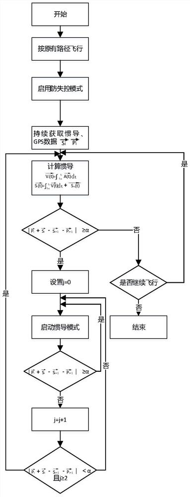
[0052] see figure 1 , the embodiment of the present invention includes:
[0053]A power tower inspection UAV anti-out-of-control method, comprising the following steps:
[0054] S1: Obtain the initial position of the GPS positioning and the real-time position of the GPS flight during the flight of the inspection drone;
[0055] S2: According to the flight acceleration measured by the UAV inertial navigation system, calculate the position of the inspection UAV; the calculation formula is as follows:
[0056]
[0057]
[0058] in, Indicates the flight acceleration of the inspection UAV measured by the inertial navigation system, Indicates the flight speed of the inspection UAV measured by the inertial navigation system, Indicates the flight displacement of the inspection UAV measured by the inertial navigation system, Indicates the flight displacement of the real-time position of the inspection UAV measured by the inertial navigation system at a moment, i=1, 2, 3....
[0059] S3: Use the initial position of GPS positioning obtained in step S1, the real-time position of GPS flight and the position of the UAV obtained in step S2 to determine whether the inspection UAV is subject to external interference; the judgment basis is the following formula:
[0060]
[0061] in, To inspect the GPS positioning position of the drone at a certain time, that is, the real-time position of the GPS flight; Check the GPS positioning position of the drone for the next moment; The position of the inspection UAV measured by the inertial navigation system at a certain moment, It is the position of the inspection UAV measured by the inertial navigation system at the next moment, and α is the threshold value, which is any value within the range of 10-30 meters;
[0062] when When , the inspection UAV is in the interference area, that is, it is subject to external interference;
[0063] when When , the inspection UAV is in a non-interference area, that is, it is not subject to external interference.
[0064] By fusing satellite navigation information and inertial navigation information, the anti-jamming capability of the inspection UAV is significantly improved.
[0065] S4: Start the GPS mode flight when the inspection drone is not disturbed; start the inertial navigation mode flight when it is disturbed. During the flight, repeat steps S1 to S3 in real time until the flight ends. include:
[0066] When the inspection UAV is not subject to external interference, that is, when the inspection UAV is in a safe flight process, it is judged whether the inspection UAV continues to fly, if otherwise, the flight is terminated, and if so, steps S1 to S3 are repeated in real time until End the flight.
[0067] When the inspection drone is interfered by external sources, the specific steps include:
[0068] S401: When the inspection UAV is disturbed by external sources, set j=0 to start the flight in inertial navigation mode, and j represents the count value of the continuous stable state of the inspection UAV;
[0069] S402: judge in real time whether the inspection drone is subject to external interference; if it is judged that the inspection drone is subject to external interference at the current moment, return to step S401;
[0070] S403: If it is judged that the inspection drone is not subject to external interference at the current moment, then set j=j+1, and after flying an integer multiple of 0.2m as the base, judge whether the condition is met And j≥2;
[0071] in To inspect the GPS positioning position of the drone at a certain time, that is, the real-time position of the GPS flight; Check the GPS positioning position of the drone for the next moment; The position of the inspection UAV measured by the inertial navigation system at a certain moment, The position of the inspection UAV measured by the inertial navigation system at the next moment, α is the threshold;
[0072] S404: If the above conditions are met, the inspection drone will switch to GPS mode to fly normally, and judge whether to continue flying;
[0073] If the above conditions are not met, the inspection UAV will continue to fly in the inertial navigation mode until it returns to normal flight.
[0074] The embodiment of the present invention also provides an anti-out-of-control system for power tower inspection drones, including:
[0075] The UAV position acquisition module is used to obtain the initial position of the GPS positioning of the inspection UAV during flight, the real-time position of the GPS flight, and the flight acceleration measured by the UAV inertial navigation system to calculate the inspection UAV s position;
[0076] The external interference judging module is used to determine whether the inspection drone is subject to external interference according to the initial position of the GPS positioning obtained by the position acquisition module of the drone, the real-time position of the GPS flight and the position of the drone;
[0077] The flight mode module is used to start the flight in GPS mode or inertial navigation mode according to the judgment result of the external interference judging module.
[0078] In addition, the embodiment of the present invention also provides an unmanned aerial vehicle including the anti-out-of-control system for the power tower inspection unmanned aerial vehicle as described above.
[0079] By monitoring the continuous flight status of the inspection UAV in real time, the navigation accuracy of the inspection UAV is significantly improved, and the UAV is guided to fly safely in the power tower inspection area.
[0080] Those skilled in the art should understand that the embodiments of the present application may be provided as methods, systems, or computer program products. Accordingly, the present application may take the form of an entirely hardware embodiment, an entirely software embodiment, or an embodiment combining software and hardware aspects. Furthermore, the present application may take the form of a computer program product embodied on one or more computer-usable storage media (including but not limited to disk storage, CD-ROM, optical storage, etc.) having computer-usable program code embodied therein.
[0081] The present application is described with reference to flowcharts and/or block diagrams of methods, apparatus (systems), and computer program products according to embodiments of the present application. It should be understood that each procedure and/or block in the flowchart and/or block diagram, and a combination of procedures and/or blocks in the flowchart and/or block diagram can be realized by computer program instructions. These computer program instructions may be provided to a general purpose computer, special purpose computer, embedded processor, or processor of other programmable data processing equipment to produce a machine such that the instructions executed by the processor of the computer or other programmable data processing equipment produce a in real process Figure 1 process or multiple processes and/or boxes Figure 1 means for the function specified in one or more boxes.
[0082] These computer program instructions may also be stored in a computer-readable memory capable of directing a computer or other programmable data processing apparatus to operate in a specific manner, such that the instructions stored in the computer-readable memory produce an article of manufacture comprising instruction means, the instructions The device is implemented in the process Figure 1 process or multiple processes and/or boxes Figure 1 function specified in one or more boxes.
[0083] These computer program instructions can also be loaded onto a computer or other programmable data processing device, causing a series of operational steps to be performed on the computer or other programmable device to produce a computer-implemented process, thereby instructions are provided for implementing the flow in Figure 1 process or multiple processes and/or boxes Figure 1 steps of the function specified in the box or boxes.
[0084] Finally, it should be noted that: the above embodiments are only used to illustrate the technical solutions of the present invention and not to limit them. Although the present invention has been described in detail with reference to the above embodiments, those of ordinary skill in the art should understand that: the present invention can still be Any modifications or equivalent replacements that do not depart from the spirit and scope of the present invention shall fall within the protection scope of the claims of the present invention.

PUM

no PUM

Description & Claims & Application Information

We can also present the details of the Description, Claims and Application information to help users get a comprehensive understanding of the technical details of the patent, such as background art, summary of invention, brief description of drawings, description of embodiments, and other original content. On the other hand, users can also determine the specific scope of protection of the technology through the list of claims; as well as understand the changes in the life cycle of the technology with the presentation of the patent timeline. Login to view more.
Why Eureka
Try Eureka