
Device for improving heat dissipation performance and automatically cleaning cooling fins for CPU heat dissipation

A technology with heat dissipation performance and automatic cleaning, which is applied in the direction of electrical digital data processing, digital processing power distribution, digital data processing components, etc. It can solve the problems of affecting the heat dissipation efficiency of the heat sink and the inability to continue to increase heat dissipation, so as to avoid heat dissipation. Efficiency, improve heat dissipation efficiency, convenient operation effect

Active Publication Date: 2021-02-26
STATE GRID TIANJIN ELECTRIC POWER
View PDF7 Cites 1 Cited by
  • Summary
  • Abstract
  • Description
  • Claims
  • Application Information

AI Technical Summary

Problems solved by technology

[0003] At present, the general CPU cooling device cannot continue to increase the heat dissipation when the CPU is overheated, and the heat dissipation area of ​​the heat sink on the general CPU cooling device is fixed, and a large amount of dust often accumulates on the heat sink when the cooling device stops, thus Attached to the surface of the heat sink greatly affects the heat dissipation efficiency of the heat sink

Method used


Image

  • Device for improving heat dissipation performance and automatically cleaning cooling fins for CPU heat dissipation
  • Device for improving heat dissipation performance and automatically cleaning cooling fins for CPU heat dissipation
  • Device for improving heat dissipation performance and automatically cleaning cooling fins for CPU heat dissipation

Examples


Embodiment Construction

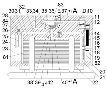
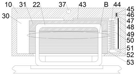
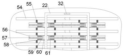
[0018] Combine below Figure 1-6 The present invention is described in detail, wherein, for the convenience of description, the orientations mentioned below are defined as follows: figure 1 The up, down, left, right, front and back directions of the projection relationship itself are the same.

[0019] combined with Figure 1-6A device for improving heat dissipation performance and automatically cleaning heat dissipation fins for CPU heat dissipation, comprising a heat dissipation casing 10, a heat dissipation cavity 30 is provided inside the heat dissipation casing 10, and a communication station is provided on the right cavity wall of the heat dissipation cavity 30 The air inlet channel 14 outside the heat dissipation casing 10 is described, and the upper side of the heat dissipation chamber 30 is also provided with an air pressure chamber 36. The heat dissipation chamber 30 is provided with a lifting mechanism 81 for improving the heat dissipation performance of the device...


PUM


Abstract

The invention discloses a device for improving heat dissipation performance and automatically cleaning cooling fins for CPU heat dissipation, which comprises a heat dissipation shell, and is simple instructure, convenient to operate and high in practicability. The problems that when a CPU is overheated, the cooling intensity cannot be continuously increased, a large amount of dust gathered on cooling fins is attached to the surfaces of the cooling fins, and consequently the cooling efficiency of the cooling fins is greatly affected are solved, when the device is used, the cooling intensity ofa radiator can be automatically increased through the device when the CPU is cooled and overheated, and the cooling efficiency of the radiator is greatly improved. When the radiator is used, part ofthe cooling fins in the radiator can be stretched out, so that the heat dissipation area of the cooling fins is increased, the heat dissipation efficiency is improved, meanwhile, the surfaces of the cooling fins can be cleaned when the cooling fins are stretched out, and when the radiator is stopped, the cooling fins are retracted to clean the surfaces of the cooling fins again; and meanwhile, thecooling fins are automatically subjected to soot blowing cleaning from top to bottom once, so that the cooling efficiency of the cooling device is prevented from being influenced by dust on the cooling fins.

Description

technical field [0001] The invention relates to the field of electronic heat sinks, in particular to a device for improving heat dissipation performance and automatically cleaning heat sinks for CPU heat dissipation. Background technique [0002] Electronic cooling devices can be divided into different types according to the power of electronic equipment, among which CPU cooling devices belong to a type of high-power cooling devices. [0003] At present, the general CPU cooling device cannot continue to increase the heat dissipation when the CPU is overheated, and the heat dissipation area of ​​the heat sink on the general CPU cooling device is fixed, and a large amount of dust often accumulates on the heat sink when the cooling device stops, thus Attached to the surface of the heat sink greatly affects the heat dissipation efficiency of the heat sink. Contents of the invention [0004] The technical problem to be solved by the present invention is to provide a device for...

Claims


Application Information

Patent Timeline
Patent Type & Authority Applications(China)
IPC IPC(8): G06F1/18G06F1/20
CPCG06F1/183G06F1/20Y02D10/00
Inventor 杨智铭
Owner STATE GRID TIANJIN ELECTRIC POWER
Learn More